05 mounting bracket assembly installation, 06 standoff control assembly installation – Tweco SC10 User Manual
Page 20
INSTALLATION PROCEDURES
3-4
Manual 0-2479
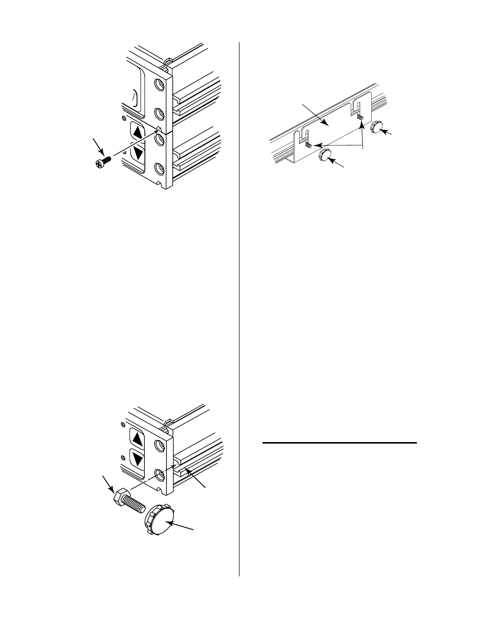
#6-32 x 1/2"
Thread Forming
Screw
A-00696
UP
DN
TORCH
RUN
PURGE
SET
Figure 3-5 Screw Installation
12. Reinstall the top enclosure cover on the top unit
securing it with the two screws removed earlier.
13. Insert two of the #10-32 x 3/8" hex head bolts into
the slots on each side of the bottom or top unit
per one of the following:
• Bracket Mounted On Top Of Surface
Insert bolts in the bottom unit if the Mounting
Bracket was installed for top surface mount-
ing.
• Bracket Mounted Underneath Surface
Insert bolts in the top unit if the Mounting
Bracket was installed for underneath surface
mounting.
The slot prevents the bolts from turning when the
knobs are installed.
Slot
Hex Head Bolt
#10-32 x 3/8"
Knob
A-00688
UP
DN
TORCH
TORCH
Figure 3-6 Bolt Installation
14. Set the assemblied units into the Mounting
Bracket being sure the four bolts are in the mount-
ing slots.
Knob
Hex Head
Bolts
Knob
Mounting Bracket
A-00674
Figure 3-7 Knob Installation
15. Place one knob on each of the bolts protruding
from the bracket slots.
16. The assemblied units can be adjusted for the best
viewing angle. The units can be tilted up to 10°.
Adjust the viewing angle per the following:
a. Loosen the four knobs sercuring the
assemblied units to the Mounting Bracket.
b. Adjust the assembled units for the desired
angle.
c. Tighten all four knobs.
d. If the angle is not correct, loosen knobs, read-
just until proper viewing angle is found, and
retighten all knobs.
3.07 Installation With TD-750
Systems
This Section describes the installation of components to
allow use of the Standoff Control with a TD-750 Cutting
System.
NOTE
For orders that included the Standoff Control as
part of the complete system these components are
factory installed. Proceed to Section 3.09 Internal
Selections.
For orders where the Standoff Control is to be added to
the TD-750 Cutting System the procedures in this sub-
section must be completed.
The TD-750 must have the proper remote output connec-
tion at the rear of the TD-750 Power Base Unit. For TD-
750 Systems that do not have the proper remote output
installed in the TD-750 Power Base Unit proceed with