Tweco SC10 User Manual
Page 23
Manual 0-2479
3-7
INSTALLATION PROCEDURES
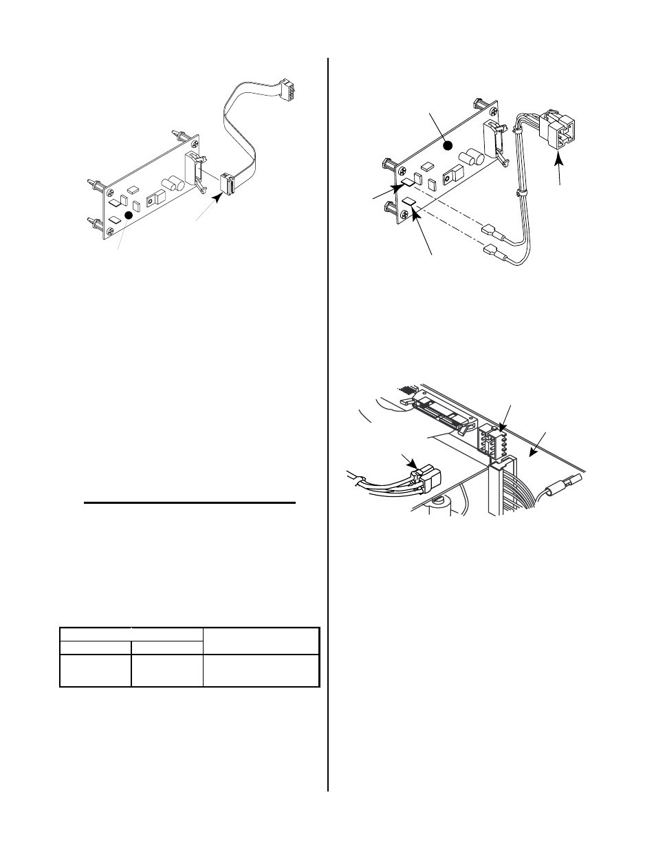
Ribbon Cable
(10-Pin)
Voltage Divider
PC Board
A-01020
Figure 3-12 Ribbon Cable Assembly
2. Route the ribbon cable to the rear of the voltage
selection plugs and through the notch in the di-
vider panel.
3. Continue routing the ribbon cable around the end
of the Analog PCB Assembly to the J11 receptacle
located at the rear panel.
4. Connect the ribbon cable to the 10-pin connector,
J32, on the side of the J11 receptacle located at the
rear panel.
Pilot Wire Harness Installation
NOTE
The wire harness is connected to the Voltage Di-
vider PCB at the factory. The information is sup-
plied to insure proper installation.
Install the Pilot Wire Harness Assembly as follows:
1. Connect the two wires from the wire harness cable
to the Voltage Divider PCB Assembly per the fol-
lowing:
W ire
V o lt a g e
P in
N u m b e r
D ivid e r C o n n e ct io n
3
5 6
P . S . +
7
5 4
P . S . -
Voltage Divider
PC Board
Connector
to Pilot PCB
(J8)
P.S. +
(56)
P.S. -
(54)
A-01021
Figure 3-13 Pilot Wire Harness Assembly
2. Connect the plug on the Wire Harness Assembly
to J8 on the Pilot PCB Assembly.
J8
Wire Harness
Connector To
Pilot PC Board
Pilot PCB
A-00527
Figure 3-14 Connection to Pilot PCB
Reinstall the enclosure cover by reversing the steps in
“Opening The Enclosure” above.
This completes the installation of the components inside
the TD-750 Control Module (CM6033).
3.08 Installation With Merlin 3000
Systems
There are no additional components that must be installed
inside the Merlin 3000 Power Supply. Proceed to Sub-
Section 3.09.