Section 3: installation procedures, 01 introduction, 02 site location – Tweco SC10 User Manual
Page 19: 03 unpacking, 04 installation - general
Manual 0-2479
3-3
INSTALLATION PROCEDURES
A-00698
J7
PLA
SM
A O
N
ARC VOLTS
RE
MO
TE
ST
AN
DO
FF
CO
NT
RO
L
T.H
.C. A
CTIV
E
PIER
CE
HT (i
nche
s)
0.1
0.3
0.4
0.5
0.2
END
OF C
UT
RET
RAC
T (%
)
0
25
75
100
UP
DN
TOR
CH
TORCH
MOD
E
MODE
LIF
TE
R
LIFTER
SPEE
D
SPEED
PIER
CE
DEL
AY (s
ec)
0.5
1
2
3
0.75
0.25
0.1
AU
TO
HT
FIN
D
HT
HI
LO
Standoff Control
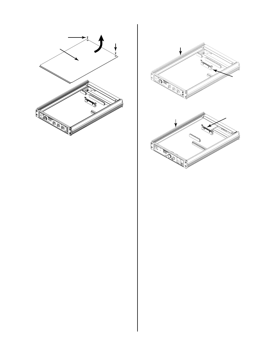
Assembly
OU
TPU
T A
MP
S
PLASMA
PLASMA
ENABLE
ENABLE
ON
STA
RT
REM
OTE
PO
WE
R S
UPP
LY C
ON
TRO
L
SD
(%
)
25
75
100
50
TRAVEL
TRAVEL
SPEED
SPEED
125
+
IPM
0-125
IPM
RU
N
PU
RG
E
SET
J5
Remote Control
Assembly
Figure 3-4 J7 and J5 Locations
9. Place the top unit on top of the bottom unit, feed-
ing the ribbon cable up through the bottom of the
top unit.
10. On the top unit, connect the other end of the rib-
bon jumper cable into one of the following:
• Standoff Control J7 if top unit
or
• Remote Control J5 if top unit
11. Secure the two units together with four #6-32x1/2
inch thread forming screws (supplied) inserted at
the front and rear panels (two screws each) in the
holes provided.
PLA
SM
A O
N
AR
C V
OL
TS
RE
MO
TE
ST
AN
DO
FF
CO
NT
RO
L
T.H
.C. A
CTIV
E
PIER
CE
HT (in
che
s)
0.1
0.3
0.4
0.5
0.2
EN
D O
F C
UT
RET
RA
CT (%
)
0
25
75
100
UP
DN
TOR
CH
TORCH
MO
DE
MODE
LIFT
ER
LIFTER
SPE
ED
SPEED
PIER
CE
DELA
Y (se
c)
0.5
1
2
3
0.75
0.25
0.1
AU
TO
HT
FIN
D
HT
HI
LO
A-00689
Screw
Screw
Cover
Figure 3-3 Cover Removal
4. Remove the top enclosure cover by lifting straight
up at the rear of the cover and pulling it towards
the rear of the unit. The front edge of the cover
fits under a lip on the front panel assembly.
5. Turn the unit over.
6. Repeat Steps 3 and 4 for the bottom enclosure
cover.
7. On the bottom unit remove the two cover mount-
ing screws on the top of the unit and remove the
top enclosure cover as in Step 4.
8. Depending on which unit is to be the bottom unit,
install the ribbon jumper cable (supplied) into one
of the following:
• Standoff Control J7 if bottom unit
or
• Remote Control J5 if bottom unit