07 installation with td-750 systems – Tweco SC10 User Manual
Page 22
INSTALLATION PROCEDURES
3-6
Manual 0-2479
It may be necessary to use a flat blade screwdriver
to pry the pin outward from the top until the
threads engage. Use a 5/16 nut driver to fully
remove the Module Assembly Pins .
A-00532
Flat Blade
Screwdriver
5/16 Inch
Nut Driver or
Socket
Figure 3-10 Pin Removal Detail
2. Lift the upper enclosure from the control mod-
ule.
Installing Voltage Divider PCB Assembly
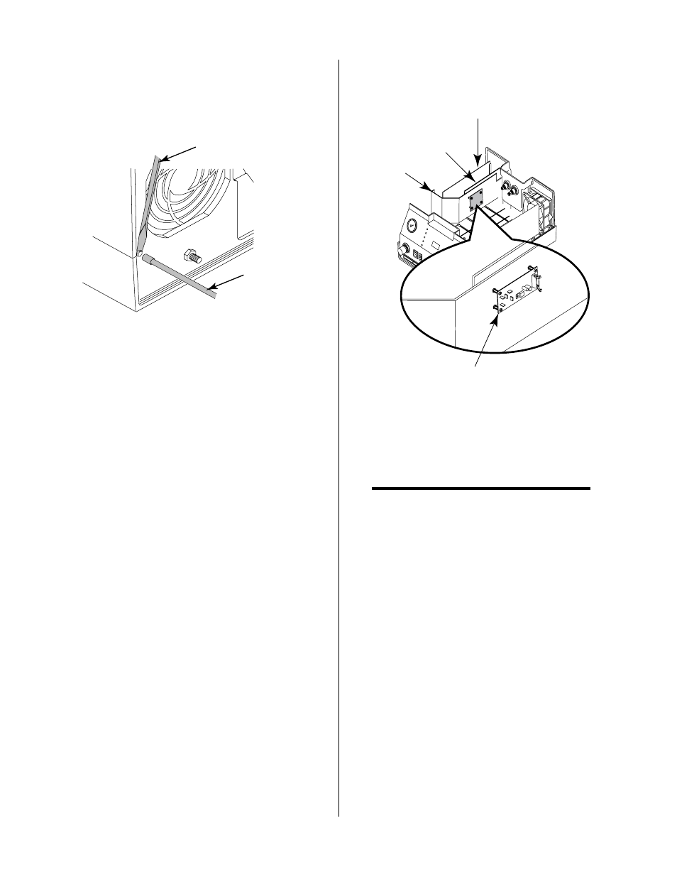
Install the Voltage Divider PCB Assembly as follows:
1. Locate the divider panel inside the control mod-
ule.
2. Locate the Voltage Divider PCB Assembly in-
cluded with the Standoff Control components.
The standoffs are factory mounted to the PC
Board.
3. Install the Voltage Divider PCB assembly onto the
divider panel placing the standoffs into the lower
four holes in the divider panel.
Voltage Divider
PCB Assembly
Divider Panel
Analog PCB
Assembly
Logic PCB
Assembly
A-01019
Figure 3-11 Voltage Divider PCB Installation
Ribbon Cable Installation
NOTE
The Ribbon Cable (10 pin) is connected to the Volt-
age Divider PCB at the factory. The information
is supplied to insure proper installation.
Install the Ribbon Cable Assembly as follows:
1. Connect the ribbon cable to the Voltage Divider
PCB per the following figure: