Tweco SC10 User Manual
Page 21
Manual 0-2479
3-5
INSTALLATION PROCEDURES
the following. With systems that already have the re-
mote output accessory installed at the rear panel proceed
to paragraph 'C. Voltage Divider PC Board Installation'.
WARNING
Disconnect primary power at the source before as-
sembling or disassembling stacked modules, indi-
vidual modules, torch parts, or torch and leads as-
semblies.
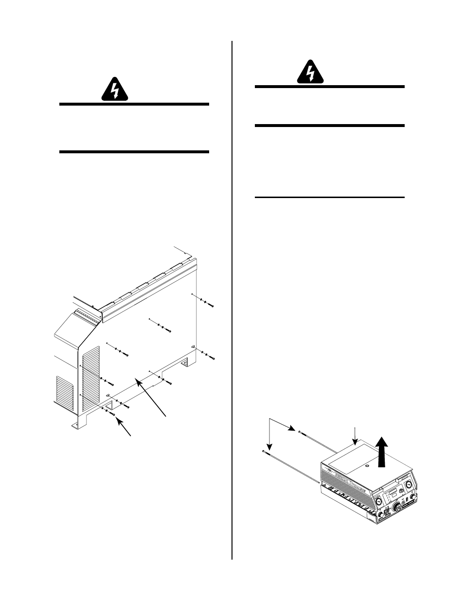
The right side of the Power Base Unit must be removed
to install the remote output assembly.
A. Removing Side Panel
1. Using a phillips head screwdriver remove the
eight screws securing the right side panel to the
Power Base Unit. The two screws in the slotted
holes need only be loosened for the panel to be
removed.
A-00675
Right Side Panel
Screws, External Star Washers
and Flat Washers (8-Places)
Figure 3-8 Screw Removal Details
2. Slide the right side panel to the right to disengage
the two screws in the slotted holes.
3. Pull the right side panel from the Power Base Unit.
B. Installation Of Remote Output
Install the remote output assembly per the instructions
supplied with the assembly.
C. Voltage Divider PC Board Installation
WARNING
Disconnect primary power at the source before as-
sembling or disassembling power supply, torch
parts, or torch and leads assemblies.
Introduction
Parts of the Standoff Control must be installed inside the
TD-750 Control Module Assembly (CM6033). The in-
structions in this section covers only the installation of
those parts.
NOTE
These instructions are for TD-750 Control Mod-
ules (CM6033) Only.
Standoff Control components to be installed inside the
Control Module include:
• Voltage Divider Wire Harness - 1 each
• #6-20 x 3/8 Phillips Head Thread Cutting Screws
- 4 each
• PC Board supports - 4 each
• Voltage Divider Ribbon Cable - 1 each
• Voltage Divider PC Board - 1 each
Opening the Enclosure
The upper half of the control module enclosure must be
removed to install the wire harness and Voltage Divider
PC Board.
1. Unscrew and remove the two module assembly
pins which secure the upper control module en-
closure to the lower.
RU
N
PU
RG
E
SE
T
ON
WO
RK
ST
AN
DA
RD
TO
RC
H
LA
TC
H
A
CURRENT
AC
TE
MP
GA
S
DC
PI
LO
T
CS
D
AM
PS
PL
AS
MA
GA
S
SE
CO
ND
AR
Y/
SI
NG
LE
G
AS
STA
K P
AK
Module Assembly Pins
H I
-TR
AN
SF
ER
Upper Enclosure
A-00049
ST
AK
II
Figure 3-9 Module Pin Removal