tekmar 667 Snow Detector & Melting Control User Manual
Page 15
15 of 28
© 2002 D 667 - 09/02
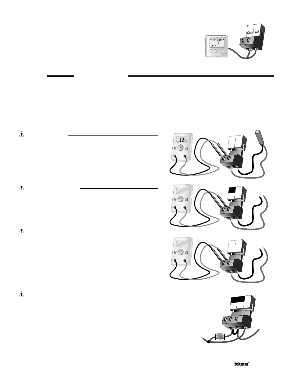
tekmar Net™ (tN2) Device
A Remote Display Module (RDM) 040 or Remote Start / Stop Module 039 can
be connected to the tekmar Net™ (tN2) input. Connect the Com terminal from
the appropriate tN2 device to the Com terminal (9) on the 667. Connect the
tN2 terminal from the appropriate tN2 device to the tN2 terminal (10) on the 667.
Note: The wires from the RDM and Remote Start / Stop Module are polarity sensi-
tive. The tN2 device does not operate correctly if the wires are reversed.
9 10
8
9
Boil Com
STEP FIVE
TESTING THE WIRING
Each terminal block must be unplugged from its header on the control before power is applied for testing. To remove the terminal
block, pull straight down from the control.
The following tests are to be performed using standard testing practices and procedures and should only be carried out by properly
trained and experienced persons.
A good quality electrical test meter, capable of reading from at least 0 – 300 V (ac) and at least 0 – 2,000,000 Ohms, is essential to
properly test the wiring and sensors.
Test The Sensors
In order to test the sensors, the actual temperature at each sensor
location must be measured. A good quality digital thermometer with
a surface temperature probe is recommended for ease of use and
accuracy. Where a digital thermometer is not available, a spare
sensor can be strap p ed alongside the one to be tested and the
readings compared. Test the sensors according to the instructions
in the Data Brochure D 070, D 079 or D 090.
Test The Power Supply
Make sure exposed wires and bare terminals are not in contact
with other wires or grounded surfaces. Turn on the p ower and
measure the voltage between the Power L and Power N terminals
(24 and 25) using an AC voltmeter, the reading should be between
103.5 and 126.5 V (ac).
Test The Powered Inputs
Melt / Idle Demand
If a Melt / Idle demand is used, measure the voltage between
the Melt/Idle Demand terminals (15 and 16). When the melting
or idling device calls for heat, you should measure between 20
and 260 V (ac) at the terminals. When the melting or idling device
is off, you should measure less than 5 V (ac).
L
N
25
Power
V
103.5 to 126.5 V (ac)
24
15 16
Melt/Idle
Demand
V
20 to 260 V (ac)
23 24
25
Sys
P1
Power
N
L
115 V (ac)
N
L
Test The Outputs
System Pump (Sys P1)
If a system pump is connected to the Sys P1 terminal (23), make sure that power
to the terminal block is off and install a jumper between the Sys P1 and Power L
terminals (23 and 24). When power is applied to the Power L and Power N terminals
(24 and 25), the system pump should start. If the pump does not turn on, check
the wiring between the terminal block and p ump and refer to any installation or
troubleshooting information supplied with the pump. If the pump operates properly,
disconnect the power and remove the jumper.