tekmar 667 Snow Detector & Melting Control User Manual
Page 14
© 2002 D 667 - 09/02
14 of 28
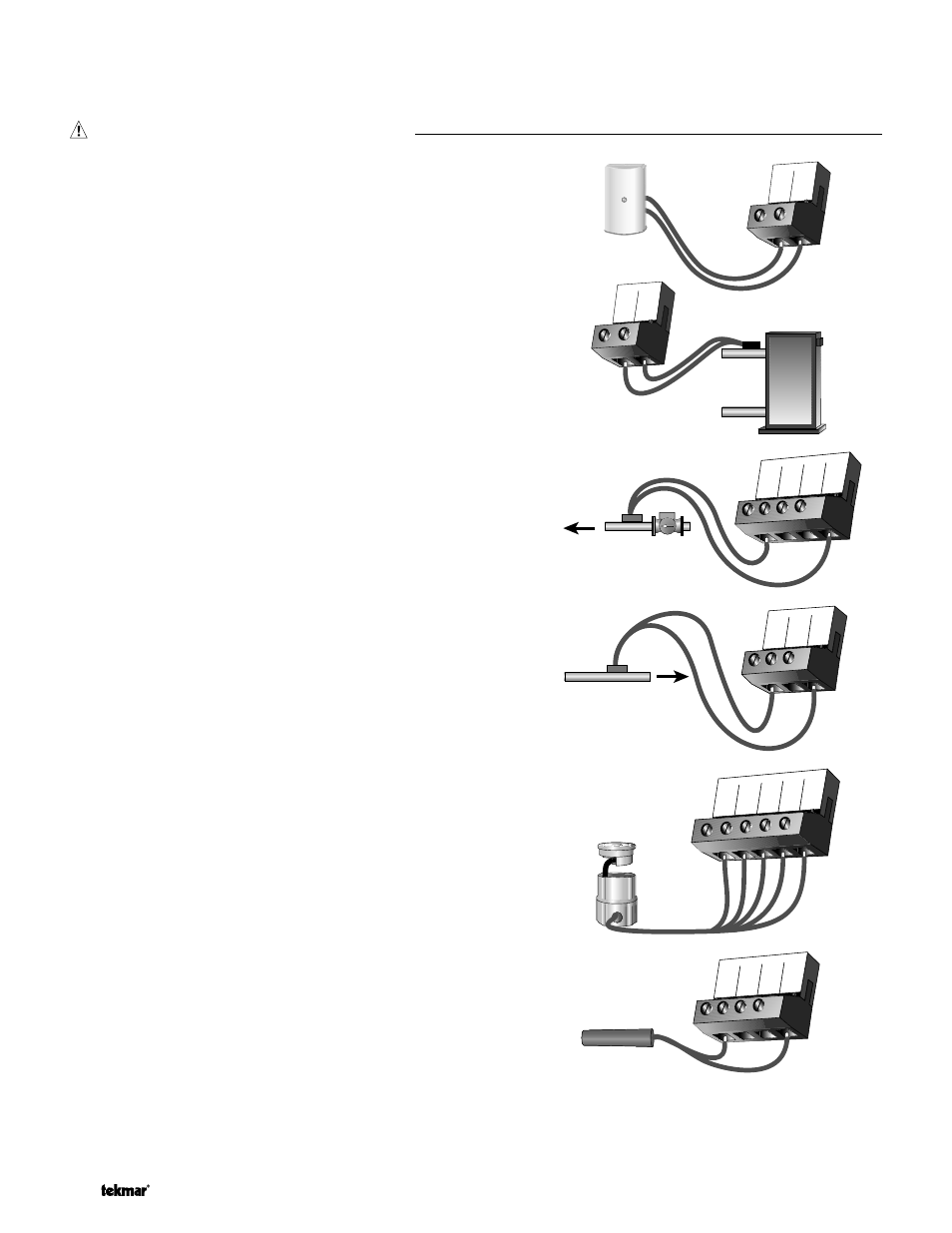
Outdoor Sensor
Connect the two wires from the Outdoor Sensor 070 to the Com and
Out terminals (13 and 14). The outdoor sensor is used by the 667 to
measure the outdoor air temperature.
Boiler Sensor
Connect the two wires from the Boiler Sensor 071 to the Boil and
Com terminals (8 and 9). The boiler sensor is used by the 667 to
measure the water temperature of the boiler.
Mixing Supply Sensor
Connect the two wires from the Mixing Supply Sensor 071 to the
Mix Sup and Com terminals (12 and 9). The mixing supply sensor is
used by the 667 to measure the fluid supply temperature after the
mixing device. Normally the sensor is attached downstream of the
mixing pump.
Mixing Return Sensor
Connect the two wires from the Mixing Return Sensor 071 to the
Com and Mix Ret terminals (9 and 11). The mixing return sensor is
used by the 667 to measure the fluid return temperature from the
snow melting slab.
EITHER: Snow / Ice Sensor 090
Connect the red wire from the sensor cable to the Red terminal (3),
connect the black wire from the sensor cable to the Blk terminal (4),
connect the blue wire from the sensor cable to the Blu terminal (5),
connect the yellow wire from the sensor cable to the Yel terminal (6)
and connect the brown wire from the sensor cable to the Brn/Slab
terminal (7). The snow / ice sensor is used by the 667 to measure
the slab surface temp erature. This sensor must be installed flush
with the slab surface and 1/2 way between the heating pipes. See
Data Brochure D 090 for installation instructions regarding the
Snow / Ice Sensor 090 and Sensor Socket 091.
OR: Slab Sensor
If a Snow / Ice Sensor 090 is not used, a slab sensor can be used.
If a slab sensor is used, connect the two wires from the slab sensor
to the Blk and Brn/Slab terminals (4 and 7). The slab sensor is used
by the 667 to measure the slab temperature.
Note: Prop er sensor p lacement is critical for correct op eration
of the 667 control. The slab sensor must be installed 1/2 way
between the heating p ip es and 1’’ (25 mm) below the surface of
the slab. Although the sensor can be installed directly into the slab,
we recommend that the sensor be installed in tubing or conduit in
such a manner that the sensor can be removed and replaced in
case of failure.
13 14
Com Out
Boiler
Sensor
8 9
Boil Com
10
9
11
12
Com
tN2 Mix
Ret
Mix
Sup
Mix Supply
Sensor
9
Com
10
tN2
11
Mix
Ret
Mix Return
Sensor
3
Red
4
Blk
5
Blu
6
Yel
7
Brn/
Slab
5
4
6
7
Blk
Blu Yel
Brn/
Slab
If a variable speed injection pump is used, connect one of the wires from the variable speed injection pump to the Var terminal
(1) on the 667. Connect the Pwr Mix terminal (2) to the live (L) side of the 115 V (ac) power source. The other wire on the variable
speed injection pump must be connected to the neutral (N) side of the 115 V (ac) power supply.
Sensor and Unpowered Input Connections
Do not apply power to these terminals as this will damage the control.