tekmar 667 Snow Detector & Melting Control User Manual
Page 13
13 of 28
© 2002 D 667 - 09/02
• Run wire from other system components (pumps, boiler, etc.) to the control.
• Run wires from the 115 V (ac) power to the control. Use a clean power source with a minimum 15 A circuit to ensure proper
operation. Multi-strand 16 AWG wire is recommended for all 115 V (ac) wiring due to its superior flexibility and ease of installa-
tion into the terminals.
STEP FOUR
––––––––––
ELECTRICAL CONNECTIONS TO THE CONTROL
The installer should test to confirm that no voltage is present at any of the wires. Push the control into the base and slide it down
until it snaps firmly into place.
Powered Input Connections
Power
25
115 V (ac)
L
N
24
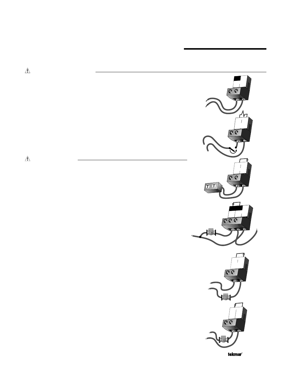
115 V (ac) Power
Connect the 115 V (ac) power supply to the Power L and Power N terminals (24
and 25). This connection provides power to the microprocessor and display of the
control. As well, this connection provides power to the Sys P1 terminal (23) from the
Power L terminal (24).
Melt / Idle Demand
To generate a melt demand or idle demand, a voltage between 24 V (ac) and
240 V (ac) must be applied across the Melt/Idle Demand terminals (15 and 16).
Output Connections
Boiler Contacts
The Boiler terminals (19 and 20) are an isolated output in the 667. There is no power
available on these terminals from the control. These terminals are used as a switch
to either make or break the boiler circuit. When the 667 requires the boiler to fire, it
closes the contact between terminals 19 and 20.
System Pump Contact (Sys P1)
The Sys P1 output terminal (23) on the 667 is a powered output. When the relay in
the 667 closes, 115 V (ac) is provided to the Sys P1 terminal (23) from the Power L
terminal (24). To operate the system pump, connect one side of the system pump
circuit to terminal 23 and the second side of the pump circuit to the neutral (N ) side
of the 115 V (ac) power supply.
System Pump Contact (System Pmp 2 )
The System Pmp 2 terminals (17 and 18) are an isolated output in the 667. There is
no power available on these terminals from the control.
If the System Pmp 2 contact is used, connect the pump circuit to the System Pmp
2 terminals (17 and 18).
Melting Contact
The Melting terminals (21 and 22) are an isolated output in the 667. There is no
power available on these terminals from the control. These terminals are used as a
switch to make or break an external circuit.
Variable Speed Injection Pump
The 667 can vary the speed of a permanent capacitor, impedance protected or
equivalent pump motor that has a locked rotor current of less than 2.4 A. Most
small wet rotor circulators are suitable as described in Essay E 021. The 667 has an
internal overload fuse which is rated at 2.5 A 250 V (ac). Contact your tekmar sales
representative for details on the repair procedures if the fuse is blown.
15
Melt / Idle
Demand
16
24 to 240 V (ac)
Boiler
20
19
Sys
P1
115 V (ac)
N
L
Power
25
L
N
24
23
17 18
L
N
115 V (ac)
System
Pmp 2
1
Var
2
Pwr
Mix
115 V (ac)
N
L