Testing the control functions, Step seven – tekmar 662 Snow Detector & Melting Control User Manual
Page 9
9
Indicator lights
Power light on
• The 120 V ac power supply is connected and the control is energized.
Remote light on
• The remote enable input is activated.
WWCO light on
• The control is in Warm Weather Cut Off.
CWCO light on
• The control is in Cold Weather Cut Off.
Melting light on
• The control is in melting mode.
Idling light on
• The control is in idling mode.
Water light on
• The snow/ice sensor is detecting the presence of water.
Maximum
∆T light • The control is limiting the temperature drop through the slab to the ∆T Max setting.
Max. Supply light
• The control is limiting the supply temperature to the Max. Supply setting.
Min. Return light
• The control is operating to keep the boiler return fluid hotter than the Min. Boil. Return setting.
Pump 1 light
• The system pump (P1) relay is on.
Pump 2 light
• The boiler pump (P2) relay is on.
Test light on
• The control is proceeding through the programmed test routine.
Opening light on
• The Open relay is on.
Closing light on
• The Close relay is on.
Boiler light on
• The Boiler relay is on.
Warning light on
• The Warning relay is on.
Power
Remote
Pump 1
Pump 2
Opening
Boiler
Warning
Closing
CWCO
Melting
Idling
WWCO
Maximum
∆T
Maximum
Supply
Minimum
Return
Water
Test
°F °C
OUTSIDE
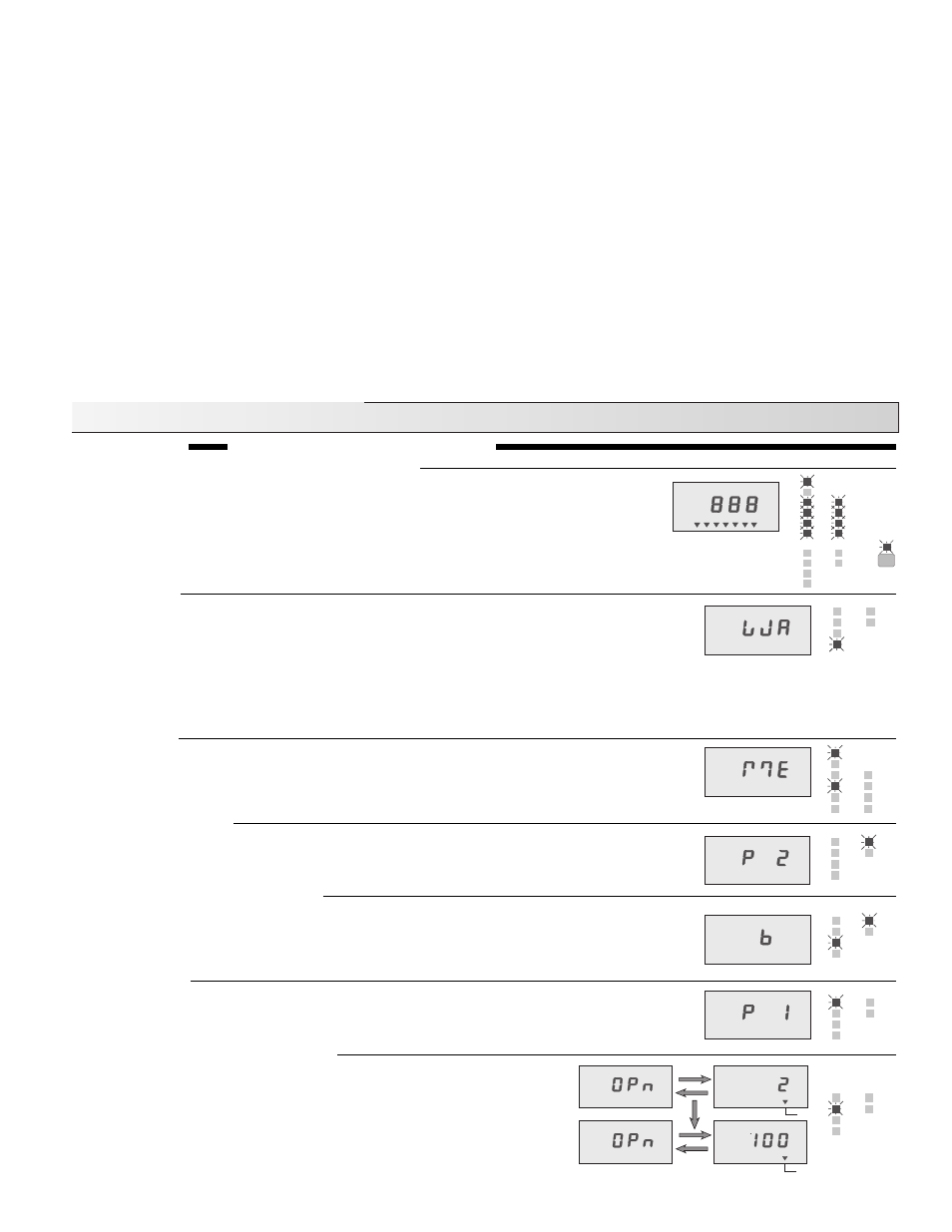
Opening on — % Output Increasing
The “Opening” light and relay turn on and the LCD flashes between
“OPn” and the current “% Output”. The time for the device to go from 0%
to 100% is set on the “Motor Speed / Pump Response” dial. During this
time, the 4-20 mA, mixing valve or variable speed pump output should
increase from 0 to 100 %. If the device does not operate or the output
does not increase, check the wiring to the device and the device itself.
Testing the Control Functions
LCD display, indicator lights and Snow/Ice Sensor
When the test button is pressed the red status lights and the LCD segments are turned on
for 7 seconds. The current to the Snow/Ice Sensor's internal heater is then increased and
if the temperature at the centre of the sensor does not rise at least 2
°F within 45 seconds
an error message is given. If the centre of the sensor is hotter than 120
°F or the outdoor
temperature is below -5
°F, the control skips this part of the test. During the 45 seconds,
the control continues with the rest of the test sequence.
Warning on
The Warning relay and light turn on and the LCD shows “W A” to indicate that the external
Warning device is being tested. If the warning device does not activate, the wiring from the
control should be checked and the warning device examined for possible faults. After 10
seconds, the “Warning” light and relay are turned off and the test continues.
Step Seven
Operational test of control functions
Note: The test routine can be halted at this, or any of the following steps, by pushing the Test button once. If this is down, the “Test”
light flashes and the control is held in a pause mode for 5 minutes after which time it automatically exits the test routine. Pushing
the “Test” button during the 5 minute pause allows the control to resume the test routine at the next step.
% Output
% Output
Melting on
The “Melting” light and relay turn on and the LCD shows “ME” to indicate that the melting
device is being tested. If the device connected to the melt relay does not activate, there
may be a fault with the wiring to the melting device or with the melting device itself - check
both. After 10 seconds, the “Melting” light and relay are turned off and the test continues.
Boiler Pump P2 on
The “Pump P2” light and relay turn on and the LCD shows “P 2” to indicate that Pump P2
is being tested. If the pump does not turn on, the wiring to the pump and the pump itself
should be checked. This pump remains on through the next part of the test sequence.
Boiler Pump P2 on and Boiler on
After Pump P2 has been on for 10 seconds, the “Boiler” light and relay are turned on and
the LCD shows “b” to indicate that the boiler is being tested. If the boiler does not turn on,
check the wiring to the boiler and the boiler itself. After another 10 seconds, both the boiler
and the boiler pump are turned off.
Pump P1 on
The Pump P1 relay and light turn on and the LCD shows “P 1” to indicate that Pump P1
is being tested. If the pump does not turn on, check the wiring to the pump and the pump
itself. After 10 seconds, the “Pump P1” light and relay turn off and the test continues.
Pump 1
Pump 2
Opening
Boiler
Warning
Closing
Pump 1
Pump 2
Opening
Boiler
Warning
Closing
Pump 1
Pump 2
Opening
Boiler
Warning
Closing
Pump 1
Pump 2
Opening
Boiler
Warning
Closing
Power
Remote
CWCO
Melting
Idling
WWCO
Maximum
∆T
Maximum
Supply
Minimum
Return
Water
Pump 1
Pum
Opening
Boiler
Warning
Clo