tekmar 662 Snow Detector & Melting Control User Manual
Page 5
5
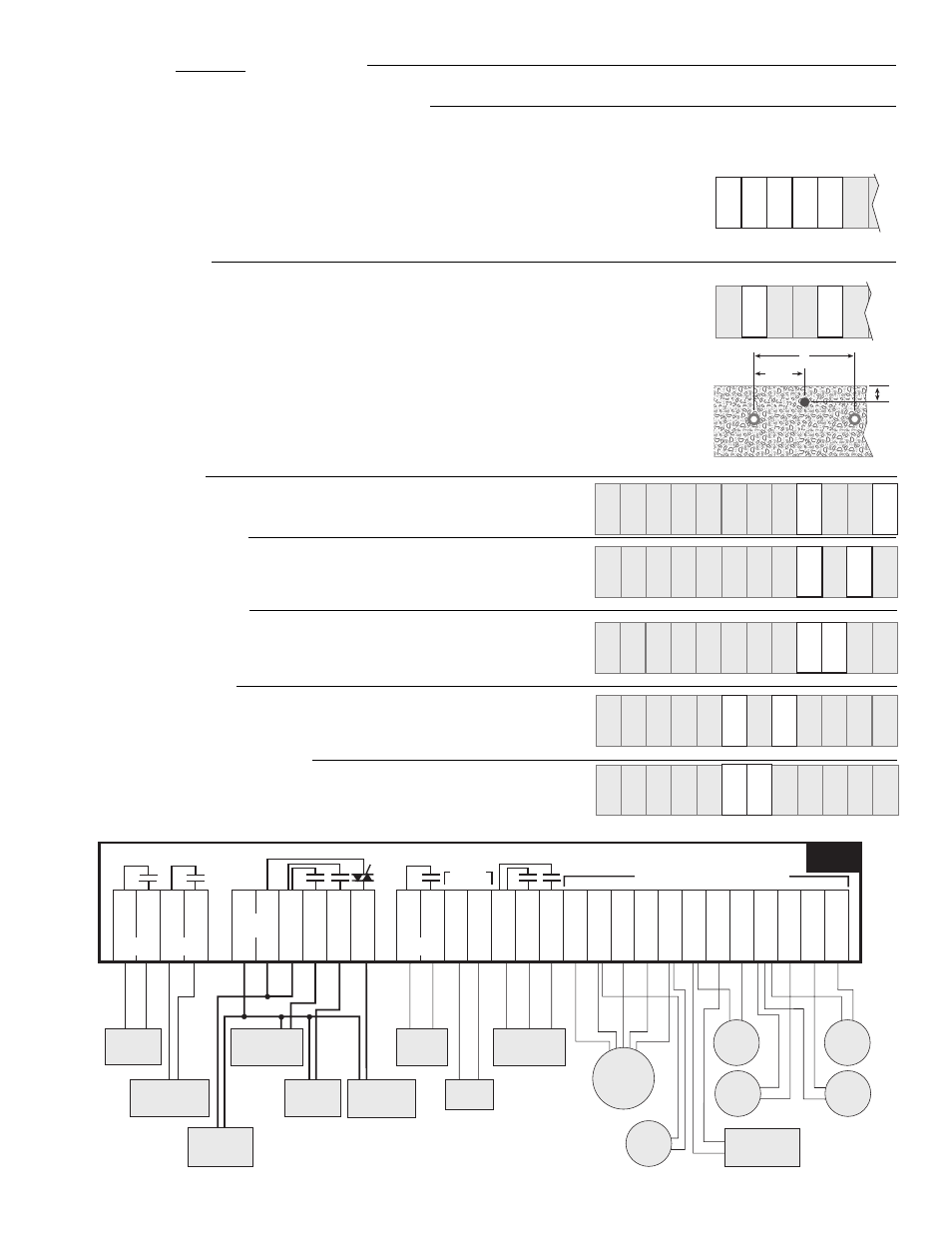
Sensor and unpowered input connections
Power should never be applied to these terminals. Damage to the control will result.
Snow/Ice Sensor 090 (Must be ordered separately)
For automatic detection of snow or ice, the tekmar Snow/Ice Sensor 090 is required. This sensor must be installed flush with
the slab surface and 1/2 way between the heating pipes.
See Data Brochure D 090 for installation instructions regarding the
Snow/Ice Sensor 090 and Sensor Socket 091.
• Connect the red wire from the sensor cable to terminal
Red Sen (18).
• Connect the black wire from the sensor cable to terminal
Blk Sen (19).
• Connect the blue wire from the sensor cable to terminal
Blu Sen (20).
• Connect the yellow wire from the sensor cable to terminal
Yel Sen (21).
• Connect the brown wire from the sensor cable to terminal
Brn Sen (22).
Slab Sensor 072
If a Snow/Ice Sensor 090 is not ordered, the Slab Sensor 072 must be installed.
With the
072 sensor, a remote enable switch turns the melting system on. Connect the two sensor
wires to terminals
Blk Sen — Brn Sen (19 and 22). The 072 sensor cable is 20 feet (6m) long
but it can be extended to a maximum overall length of 1000 feet (300 m). If extension becomes
necessary, splices should be properly soldered and waterproofed and be protected in an
accessible, waterproof junction box. Use at least 18 AWG wire for extensions.
Important Note: Proper sensor placement is critical for correct operation of the 662
control. The Slab Sensor 072 must be installed
1/2 way between the heating pipes and
1" (25 mm) below the surface of the slab. Although the 072 sensor can be placed directly
into the slab, we recommend that the sensor be installed in tubing or conduit in such a
manner that the sensor can be removed and replaced in case of failure.
Outdoor Sensor
• Connect the two wires from the Outdoor Sensor 070 to the
terminals
Com Sen — Out Sen (26 and 29).
System Supply Sensor
• Connect the two wires from the Universal Sensor 071 – which should
be mounted on the system supply pipe to the slab – to terminals
Com
Sen — Sup Sen (26 and 28).
System Return Sensor
• Connect the two wires from the Universal Sensor 071 – which should
be mounted on the system return pipe from the slab – to terminals
Com Sen — Ret Sen (26 and 27).
Boiler Return Sensor
• Connect the two wires from the Universal Sensor 071 – which should
be mounted on the return pipe to the boiler– to terminals
Com Sen
— Bret Sen (23 and 25).
Remote Enable Signal (Optional)
• If a remote device is used to enable the control, connect the two
wires from the device to terminals
Com Sen — Rem Sen (23 and 24).
23 2
Com
Sen
R
E
Sen
18
21
Sen Sen
Red
Blu Yel
20
Sen
Brn
22
19
Sen
Blk
23 2
Com
Sen
Re
E
Sen
18 19
21
Sen Sen Sen Sen
Blk
Brn
Red
Blu Yel
20
22
Note: This is not a wiring diagram. For
detailed wiring schematics refer to the
Application Brochures A 662.
23 24 25
26
27
28
Com
Sen
Rem
En
Bret
Sen
Com
Sen
Ret
Sen
Sup
Sen
Out
Sen
29
Sen
18 19
21
Sen Sen Sen Sen
Blk
Brn
Red
Blu Yel
20
22
23 24 25
26
27 28
Com
Sen
Rem
En
Bret
Sen
Com
Sen
Ret
Sen
Sup
Sen
Out
Sen
29
Sen
18 19
21
Sen Sen Sen Sen
Blk
Brn
Red
Blu Yel
20
22
23 24 25
28
Com
Sen
Rem
En
Bret
Sen
Sup
Sen
Out
Sen
29
Sen
18 19
21
Sen Sen Sen Sen
Blk
Brn
Red
Blu Yel
20
22
26 27
Com
Sen
Ret
Sen
23
24
25
26 27 28
Com
Sen
Rem
En
Bret
Sen
Com
Sen
Ret
Sen
Sup
Sen
Out
Sen
29
Sen
18 19
21
Sen Sen Sen Sen
Blk
Brn
Red
Blu Yel
20
22
23 24
25 26 27 28
Com
Sen
Rem
En
Bret
Sen
Com
Sen
Ret
Sen
Sup
Sen
Out
Sen
29
Sen
18 19
21
Sen Sen Sen Sen
Blk
Brn
Red
Blu Yel
20
22
X
1/2
X
1"
(25 mm)
Y
ellow
Brown
Red
Black
Blue
OR
System Pump
relay closes to turn
on System Pump
Outdoor
Sensor
070
Remote Enable
signal
(Optional)
Boiler
Return
Sensor
071
System
Return
Sensor
071
Supply
Sensor
071
Snow/Ice
Sensor
090
Variable Speed
Pump
output varies from
0% to 100%
4 to 20 mA
modulating
output
Boiler
relay closes
to turn on
boiler
Actuating Motor
relays close to
operate Mixing
Valve motor
Boiler Pump
relay closes to
turn on Boiler
Pump
Warning
relay closes when a
sensor fault occurs
Melt
relay closes
when in
melting mode
Power
Requirements
120 V ac
± 10%,
50/60Hz.
Slab
Sensor 072
or 073
1 2 3 4
Melt Warning
1 2
4
17 18 19 20 21 22 23 24 25 26 27
Red
Sen
Blk
Sen
Blu
Sen
Yel
Sen
Brn
Sen
Com
Sen
Bret
Sen
Ret
Sen
Com
Sen
Rem
En
Sup
Sen
Out
Sen
28
11 12 13 14 15 16
Boiler
4-20
+
4-20
-
Opn
Mix
Cls
Mix
10
Com
Pmp
P1
Pmp
P2
Pmp
Var
Pmp
L
N
Power
5 6 7 8 9
6A
10A
10A
2.2A
6A
Do not apply power here
10A
662
Com
Mix
29
1000
Ω
10A 10A