Step four – tekmar 662 Snow Detector & Melting Control User Manual
Page 4
4
Step Four
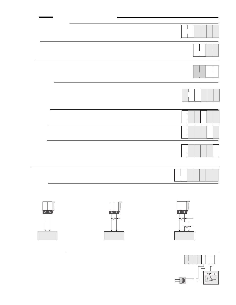
Electrical connections to the control
Power and output connections
• The installer should test to confirm no voltage is present at any of the wires.
• Install the control back into the base by sliding it down until it snaps in firmly.
• Connect the 120 V ac power supply to terminals
Power N — L (5 and 6).
Melt Output
• Connect the melting device to terminals
Melt (1 and 2). These terminals lead to an unpowered
(dry) relay contact inside the control which closes when the control enters melting mode. The
most common devices to be enabled by the 662 are pumps, heating devices or other controls.
Warning
• If desired, connect a warning device to terminals
Warning (3 and 4). These terminals lead to
a dry relay contact inside the control which closes when there is a sensor or wiring fault.
Caution: The 662 is an operating control and is not certified as a safety device. If safety
considerations are critical, a separate alarm system must be installed.
Pump Power Supply
• Terminal
Com Pmp (7) is the common power supply terminal for both terminals P1 Pmp (8)
and
P2 Pmp (9).
• If the pumps P1 and P2 are operated from the same 120 V ac power supply as the control,
connect the terminal
Power L (6) to the terminal Com Pmp (7).
• If a separate power supply is required for P1 and/or P2, contact tekmar for details.
System Pump P1
• Connect the System Pump to terminals
Power N — P1 Pmp (5 and 8). These terminals lead
to a dry relay contact which closes when the control requires System Pump operation.
Boiler Pump P2
• Connect the Boiler Pump to terminals
Power N — P2 Pmp (5 and 9). These terminals lead
to a dry relay contact which closes when the control requires Boiler Pump operation.
Variable Speed
• Connect the variable speed pump to terminals
Power N —Var Pmp (5 and 10). Pumps
operated by this circuit must be permanent capacitor, impedance protected with a locked rotor
current less than 2.2 amps. The Snow Detector & Melting Control 662 has an internal 2.5 amp
fuse for overload protection.
This fuse is not field replaceable. Contact tekmar for details on
return and repair procedures if this fuse is blown.
Boiler
• Connect the boiler or the boiler control to the terminals
Boiler (11 and 12). These terminals
lead to a dry relay contact which closes when the control requires boiler operation.
4-20 mA Device
• Connect the positive 4 - 20 mA lead to terminal
4-20 + (13) and the negative 4 - 20 mA lead to terminal 4 - 20 – (14). Maximum
resistance allowed in the 4 - 20 mA circuit is 1000
Ω. The 4 - 20 mA output can be converted to a voltage output by connecting
a resistor between terminals 13 and 14.
1
2
Melt
3
4
Warning
7
8
9
Var
Pmp
Com
Pmp
P2
Pmp
P1
Pmp
10
5
6
Power
N L
1
2
Melt
3
4
Warning
9
Var
Pmp
P2
Pmp
10
7
Com
Pmp
6
5
Po
wer
N
L
8
P1
Pmp
14
13
4-20
+
Boiler
11 12
16
15
Opn
Mix
Com
Mix
17
Cls
Mix
4-20
–
Floating Action Mixing Valve
• Connect one side (R) of a 24 V ac transformer to terminal
Com Mix (15).
• Connect the (C) side of the transformer to terminal
N/C on the tekmar 010 Actuating Motor.
For other makes of actuating motors, refer to the manufacturers' installation instructions.
• Connect the OPEN terminal of the Actuating Motor (CCW) to the terminal
Opn Mix (16) on
the control. This terminal leads to a relay contact which closes to provide 24 V ac to open
the valve.
• Connect the CLOSE terminal of the Actuating Motor (CW) to the terminal
Cls Mix (17) on
the control. This terminal leads to a relay contact which closes to provide 24 V ac to close
the valve.
14
13
4-20
+
Boiler
11 12
16
Cls
Mix
Opn
Mix
24Vac
N
L
Separate Class II
Transformer
17
Com
Mix
4-20
–
C
R
15
type 010
M
N
1
2
C
66.5
Ω resistor
237
Ω resistor
13
+
4-20
1
Converting the 4 - 20 mA Output to
Operate a 0 - 135
Ω Actuating Motor
0 - 135
Ω "Slidewire"
Actuating Motor
R
B
W
14
C
M
–
4-20
Connection to Operate
a 4 - 20 mA Device
14
13
+
4-20
1
4 - 20 mA
Actuating Motor
+
–
C
M
–
4-20
OR
500
Ω resistor
4-20 mA converted
to 2-10 Vdc output
250
Ω resistor
4-20 mA converted
to 1-5 Vdc output
Converting the 4 - 20 mA Output to
Operate a 1 - 5 Vdc or 2 - 10 Vdc Device
14
13
+
4-20
C
M
1
1-5 or 2-10 Vdc
Actuating Motor
+
–
–
4-20
8
9
Var
Pmp
P2
Pmp
P1
Pmp
10
5
Po
wer
N
L
7
Com
Pmp
6
Var
Pmp
10
7
Com
Pmp
6
5
Po
wer
N
L
9
P2
Pmp
8
P1
Pmp
7
Com
Pmp
6
5
Po
wer
N
L
9
P2
Pmp
8
P1
Pmp
Var
Pmp
10