Sequence of operation – tekmar 662 Snow Detector & Melting Control User Manual
Page 2
2
In order for this control to operate effectively, it must be installed in a well designed melting system. The Application Brochures A 662
provide a series of schematics which can be used with this control. Any deviations from these drawings must be discussed with a tekmar
factory representative to ensure that system performance is not compromised. The application drawings are not final designs - each
component within the system must be correctly sized for the control to operate effectively. It is important that the sequence of operation
and the application drawings for this control are fully understood to ensure that the control selected is compatible with its intended use.
Power
Remote
Pump 1
Pump 2
Opening
Boiler
Warning
Closing
CWCO
Melting
Idling
WWCO
Maximum
∆T
Maximum
Supply
Minimum
Return
Water
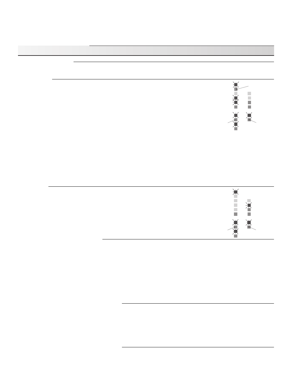
Closing light is on
if the melting
system requires
less heat
Opening light is
on if the melting
system requires
more heat
If a remote signal is
present, the Remote
light turns on
Power
Remote
Pump 1
Pump 2
Opening
Boiler
Warning
Closing
CWCO
Melting
Idling
WWCO
Maximum
∆T
Maximum
Supply
Minimum
Return
Water
Closing light is on
if the melting
system requires
less heat
Opening light is
on if the melting
system requires
more heat
Sequence of Operation
Powering up the control
After the Snow Detector & Melting Control 662 is powered up, the red status lights and the LCD segments are turned on for 7 seconds.
The control then displays the “Outdoor” temperature.
Melting Mode
Operation using a Snow/ Ice Sensor 090 - The control continually monitors the Snow/Ice Sensor
090. When water is detected, the “Water” light turns on and if the control is not in WWCO or
CWCO (see page 3 for an explanation of these terms), melting mode begins.
Operation using a Remote Enable - Melting mode can also be initiated if a remote enable signal
is present (terminals Com Sen and Rem Sen shorted together) and the control is not in WWCO
or CWCO. The remote enable is typically used with multiple Snow Melting Controls and Snow/
Ice Sensors. It can be also be used to manually turn the melting system on by wiring a switch
between the remote terminals. A remote enable switch must be installed when a Slab
Sensor 072 is used as this sensor cannot detect water.
Once the control is in melting mode, the Melting relay and boiler pump (relay P2 Pmp) are turned
on. After a 4 second delay, the system pump (relay P1 Pmp) is turned on and after 8 seconds, heat is applied to the snow melt system
through either a variable speed pump, a floating action mixing valve or a 4-20 mA device. The opening and closing lights indicate
whether the control is increasing or decreasing the heat applied to the snow melt system. Essay E 021 compares the use of these
devices for controlling the system temperature and also discusses the sizing and operation of the variable speed pump. Information
on floating action can be found in Essay E 000. The 4-20 mA, variable speed pump and mixing valve outputs operate simultaneously.
The 4-20 mA output can therefore be used to provide a remote readout of the pump or valve operation. The control remains in melting
mode until no water is detected for at least 30 seconds and the slab is up to temperature for at least 30 minutes. Cold Weather or
Warm Weather Cut Off can also terminate melting mode. When the control exits melting mode the boiler and system pumps are
operated for an additional 90 seconds to purge the boiler. If the control switches from melting to idling mode, the boiler is not purged.
Idling Mode
When the melting system starts off from a cold temperature, the time required for the slab to reach
“Melting” temperature can be excessive. To decrease this start up time, the slab can be maintained
at an “Idling” temperature until melting is required. The idling feature is also useful for preventing
frost and light ice formation. When the control is in idling mode, control operation is similar to melting
mode except the “Melting” and “Water” lights are off and the “Idling” light is on.
Snow melt system protection features
The 662 control has several features for protection of the snow melt system:
- to protect the slab from cracking due to thermal stresses, the control limits the rate of heat applied to the slab through a “
∆T Max”
setting. The
∆T represents the difference between the slab supply and return fluid temperatures which are measured by the control.
If this temperature difference approaches the “
∆T Max” setting, the “Maximum ∆T” light turns on and the control operates the valve
or pump to maintain the
∆T at the “∆T Max” setting.
- to protect the piping and other components in the system, the control limits the supply temperature to a “Max. Supply” setting. When
the melt system supply temperature approaches the maximum supply setting, the “Maximum Supply” light turns on and the control
operates the valve or pump to reduce the supply temperature.
- to prevent the flue gases in the boiler from condensing, the control limits the boiler return temperature to a “Min. Boil. Return” setting.
When the boiler return temperature approaches this setting, the “Minimum Return” light turns on and the control operates the valve
or pump to increase the boiler return temperature.
∆
T compensation for changes in fluid viscosity
Glycol solutions used in snow melt systems have widely varying viscosities between high and low temperatures. As the glycol solution
temperature drops, viscosity increases causing a reduction in flow rate. This reduction in flow rate reduces the rate of heat output
if the fluid temperature drop across the slab (
∆T) remains constant. To compensate for this, the control increases the Maximum ∆T.
This compensation is only applied when the fluid temperature is below 30
°F, which is the temperature at which the viscosity of a typical
40% ethylene glycol / 60% water solution starts to increase significantly. The compensation feature is designed for fluids containing
40% ethylene glycol or 30 % propylene glycol; however, if the glycol percentage in the solution is lower than these values, the quality
of heat regulation is not significantly affected. When the control is compensating for viscosity changes, the “Maximum
∆T” light flashes.
Ramping the
∆
T during melting system start up
When the control turns on the melting system, the “Target
∆T” is slowly ramped up to the maximum ∆T to prevent thermal shock of
the slab. If the temperature of the fluid returning to the boiler (source) is sufficient, the ramping time is less than 17 minutes. If the
heat source is not dedicated to snow melting and there are other heat demands on the source, the ramping time may be longer.