Sequence of operation, Defi nitions – tekmar 279 Steam Control User Manual
Page 4
©
2010 D
279
-
05/10
4
of
24
Establishing Steam
Section B
Sequence of Operation
Powering up the control
When the control is powered on, all segments in the LCD
are turned on for 2 seconds. Next, the control displays the
control type number in the LCD for 2 seconds. Next, the
software version is displayed for 2 seconds. Last, the control
enters into the normal operating mode.
Boiler Contact Operation
In single on-off steam boiler applications, the control uses
the boiler contact to connect to the thermostat terminals
(T-T) on the boiler. The pressure control and all other safety
devices and circuits must continue to be wired in series to
the burner circuit. The boiler contact on the control is used
to turn on or off the steam boiler burner.
In steam valve applications, the boiler contact on the control
is used to power the valve motor to open the valve. When
power is removed, the valve must close.
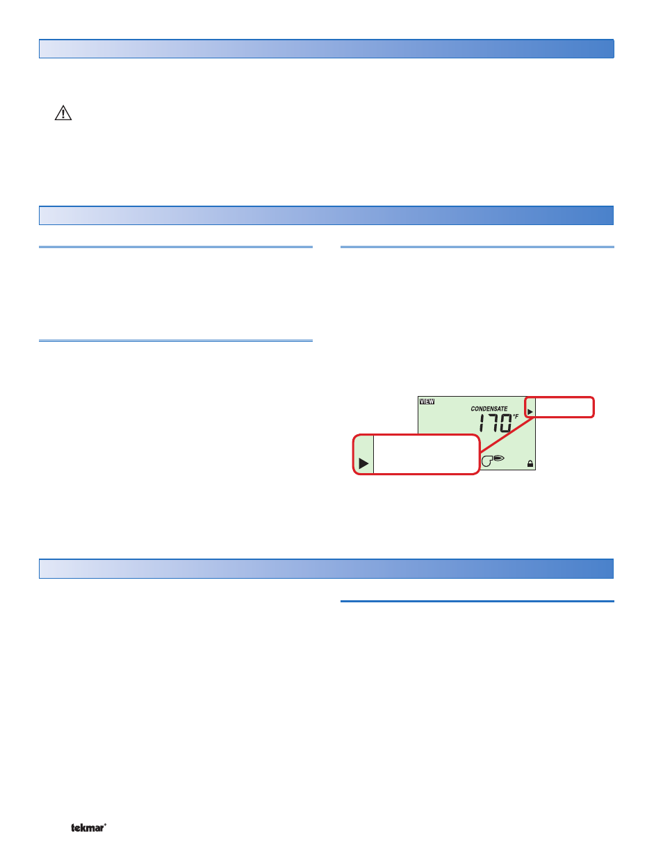
Status
The control has a status field on the right hand side of the
control. A pointer is shown in the status field once the boiler
contact is turned on. The pointer indicates at which point
of the steam heating system cycle the control is currently
operating at.
The steps are as follows:
Establishing Steam
Heat Cycle
Lockout Differential
DHW Tankless Coil Heating
STATUS
Establishing Steam
Heat Cycle
Lockout Differential
DHW Tankless Coil Heating
STATUS
Establishing Steam
Each of these steps are described in detail in the following
sections.
•
•
•
•
General
Section A
In steam heating systems, there is a time delay between
when the steam boiler or steam valve is turned on and
when the steam finally reaches the furthest radiator in the
system. It is important for the control to determine how
long this time delay is in order to ensure proper heating in
all rooms. When heat is required, the control activates the
boiler relay but does not consider the heating cycle to start
until steam has been established at the furthest radiator.
While the control is waiting to establish steam, the Status
field will have a pointer indicating Establishing Steam.
The control can use one of two methods to determine the
time to establish steam.
Condensate Return Sensor
The Universal Sensor 071 included with the control can be
used to measure the temperature of the condensate return
pipe. In a one pipe system, it is recommended to install the
sensor on the bottom of the pipe just before it enters the last
radiator. In a two pipe system, it is recommended to install
the Condensate Sensor on the bottom of the condensate
return pipe of the radiator furthest from the boiler. In cases
where access to the furthest radiator is not possible, an
alternative is to locate the sensor on the bottom of the
condensate return pipe in the mechanical room. Once the
condensate sensor is installed, ensure the Condensate
Sensor /Off Switch Setting to Condensate Sensor. The
measured condensate return temperature reading is visible
in the View menu.
Defi nitions
The following defined terms and symbols are used throughout this manual to bring attention to the presence of hazards of
various risk levels, or to important information concerning the life of the product.
Caution: Refer to accompanying documents.