Step five — testing the wiring – tekmar 279 Steam Control User Manual
Page 13
13 of 24
© 2010 D 279 - 05/10
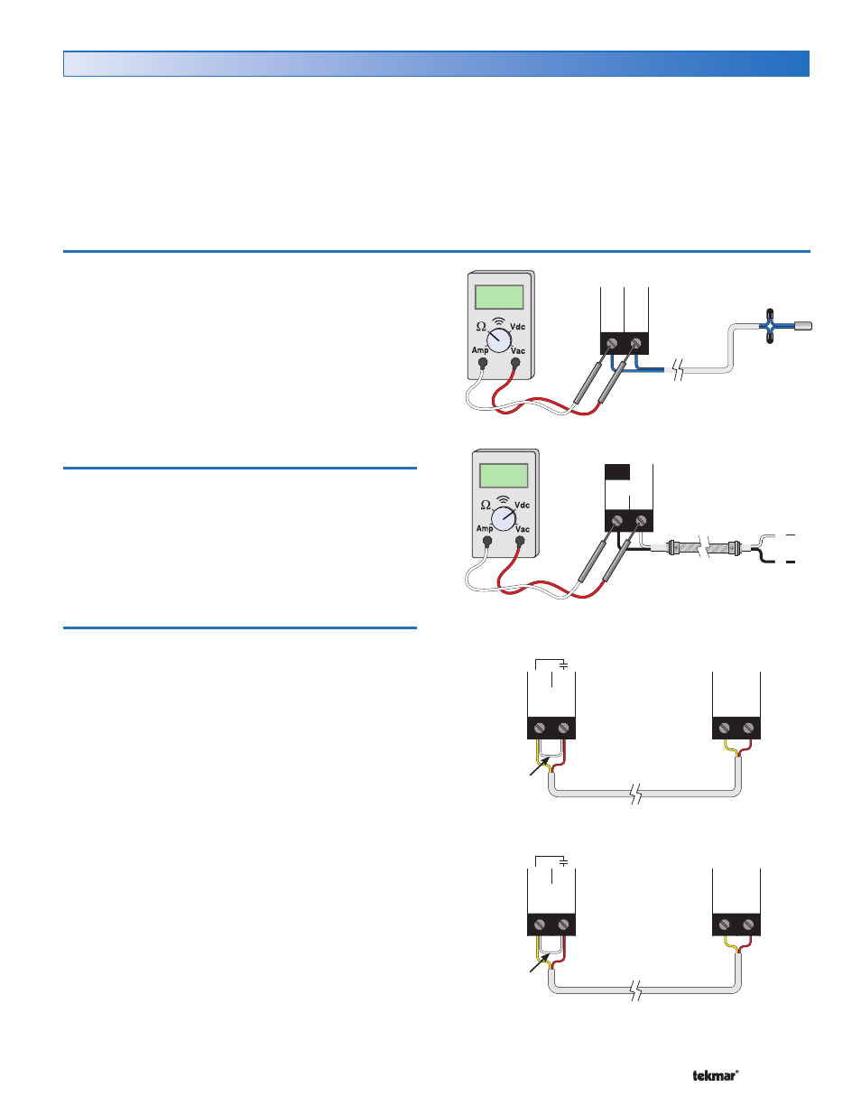
In order to test the sensors, the actual temperature at
each sensor location must be measured. A good quality
digital thermometer with a surface temperature probe is
recommended for ease of use and accuracy. Where a
digital thermometer is not available, a spare sensor can be
strapped alongside the one to be tested and the readings
compared. Test the sensors according to the instructions
in the Data Brochure D 070.
Test the Power Supply
Make sure exposed wires and bare terminals are not in
contact with other wires or grounded surfaces. Turn on the
power and measure the voltage between the Power L and
Power N terminals (1 and 2) using an AC voltmeter, the
reading should be between 103.5 and 126.5 V (ac).
Test the Outputs
Alert 1
If a security system, alarm panel, or telephone dialer
is connected to the Alert 1 terminals (3 and 4), install a
jumper wire between the terminals. The security system,
alarm panel, or telephone dialer should respond. If the
security system, alarm panel, or telephone dialer does not
respond properly, refer to any installation or troubleshooting
information supplied with the security system, alarm panel,
or telephone dialer equipment. If the security system, alarm
panel, or telephone dialer operates properly, then remove
the jumper wire.
Alert 2
If a security system, alarm panel, or telephone dialer
is connected to the Alert 2 terminals (5 and 6), install a
jumper wire between the terminals. The security system,
alarm panel, or telephone dialer should respond. If the
security system, alarm panel, or telephone dialer does not
respond properly, refer to any installation or troubleshooting
information supplied with the security system, alarm panel,
or telephone dialer equipment. If the security system, alarm
panel, or telephone dialer operates properly, remove the
jumper wire.
Step Five — Testing the Wiring
General
Each terminal block must be unplugged from its header on
the control before power is applied for testing. To remove
the terminal block, pull straight down from the control.
The following tests are to be performed using standard
testing practices and procedures and should only be carried
out by properly trained and experienced persons.
A good quality electrical test meter, capable of reading from
at least 0 – 300 V (ac) and at least 0 – 2,000,000 Ohms, is
essential to properly test the wiring and sensors.
Test the Sensors
14
15
Com Cdn
Sen Sen
Ω
N
L
1
2
Power
L
N
V
3
4
Alert 1
High
Alert
Monitor
Device
Jumper wire
between
terminals
5
6
Alert 2
Low
Alert
Monitor
Device
Jumper wire
between
terminals