Step three — rough-in wiring, Step four — electrical connections to the control – tekmar 279 Steam Control User Manual
Page 11
11 of 24
© 2010 D 279 - 05/10
All electrical wiring terminates in the control base wiring
chamber. The base has standard 7/8” (22 mm) knockouts,
which accept common wiring hardware and conduit fittings.
Before removing the knockouts, check the wiring diagram
and select those sections of the chamber with common
voltages. Do not allow the wiring to cross between sections
as the wires will interfere with safety dividers which should
be installed at a later time.
Power must not be applied to any of the wires during the
rough-in wiring stage.
All wires are to be stripped to a length of 3/8” (9 mm) to
ensure proper connection to the control.
Install the Outdoor Sensor 070 according to the installation
instructions in the Data Brochure D 070 and run the wiring
back to the control.
•
•
Install the Indoor Sensor 076, 077, or 084 according to the
installation instruction in the Data Brochure D 076, D 077,
or D 084 and run the wiring back to the control.
Install the Condensate Sensor 071 according to the
installation instructions in the Data Brochure D 070 and
run the wiring back to the control.
Install the DHW Tankless Coil Sensor 082 according to
the installation instructions in the Data Brochure D 070
and run the wiring back to the control.
Run wires from any security system, alarm panel, or
telephone dialer back to the control.
Run wires from the 115 V (ac) power to the control. Use
a clean power source with a 15 A circuit to ensure proper
operation. Multi-strand 16 AWG wire is recommended for
all 115 V (ac) wiring due to its superior flexibility and ease
of installation into the terminals.
•
•
•
•
•
Step Three — Rough-in Wiring
General
The installer should test to confirm that no voltage is present at any of the wires. Push the control into the base and slide
it down until it snaps firmly into place.
Step Four — Electrical Connections to the Control
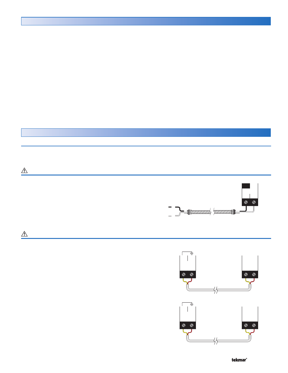
Powered Input Connections
Terminals 1, 2
115 V (ac) Power
Connect the 115 V (ac) power supply to the Power L and
Power N terminals (1 and 2). This connection provides
power to the microprocessor and display of the control.
Output Connections
Terminals 3 - 8
Alert 1
The Alert 1 terminals (3 and 4) are isolated outputs in the
control. There is no power available on these terminals from
the control. These terminals are to be used as a switch to
either make or break a signal to a security system, alarm
panel, or telephone dialer. Since this is an isolated contact,
it may switch a voltage up to 230 V (ac).
Note: Alert 1 requires a minimum current of 0.1 A in order
to keep the contact functioning properly.
Alert 2
The Alert 2 terminals (5 and 6) are isolated outputs in the
control. There is no power available on these terminals from
the control. These terminals are to be used as a switch to
either make or break a signal to a security system, alarm
panel, or telephone dialer. Since this is an isolated contact,
it may switch a voltage up to 230 V (ac).
Note: Alert 2 requires a minimum current of 0.1 A in order
to keep the contact functioning properly.
Steam
Control 279
Alert
Monitor
Device
3
4
Alert 1
High
Steam
Control 279
Alert
Monitor
Device
5
6
Alert 2
Low
N
L
1
2
Power
L
N
Steam
Control 279
115 V (ac)