tekmar 268 Boiler Control User Manual
Page 21
21 of 32
© 2010
D 268 - 11/10
1
2 3
4
Com
–
Boil
Ret
Out
+
Boil
Sup
500Ω
0 - 10 V (dc)
0 - 20 mA
OR
V
9
Power
L
N
Prim
P1
10 11
L
N
13
12
C.A./
Alert
M
24 to 230 V (ac)
L
N
OR
15
14
Relay
1
1
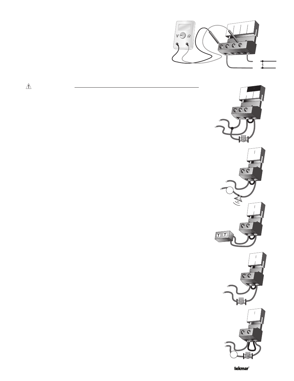
Test The Outputs
Primary Pump
(Prim P1)
If a primary pump is connected to the Prim P1 terminal (11), make sure that power
to the terminal block is off and install a jumper between the Power L and Prim P1
terminals (10 and 11). When power is applied to the Power N and Power L terminals
(9 and 10), the primary pump should start. If the pump does not turn on, check the wiring
between the terminal block and pump and refer to any installation or troubleshooting
information supplied with the pump. If the pump operates properly, disconnect the
power and remove the jumper.
Combustion Air or Alert
(C.A. / Alert)
If a combustion air damper or an alert is connected to the C.A. / Alert terminals (12 and 13),
make sure power to the damper or alert circuit is off and install a jumper between
terminals (12 and 13). When the circuit is powered up, the combustion air damper
should open or the alert should activate. If the damper or the alert fails to operate,
check the wiring between the terminals and the damper or the alert and refer to any
installation or troubleshooting information supplied with these devices. If the damper
or the alert operates properly, disconnect the power and remove the jumper.
Relay 1 to Relay 9
If a boiler stage is connected to the Relay 1 terminals (14 and 15), make sure power
to the boiler circuit is off, and install a jumper between the terminals. When the boiler
circuit is powered up, the boiler should fire. If the boiler does not turn on, refer to
any installation or troubleshooting information supplied with the boiler. (The boiler may
have a flow switch that prevents firing until the primary pump (P1) or boiler pump is
running). If the boiler operates properly, disconnect the power and remove the jumper.
If a boiler pump is connected to the Relay 1 terminals (14 and 15), make sure that
power to the terminal block is off and install a jumper between the terminals. When
power is applied to circuit, the boiler pump should start. If the pump does not turn on,
check the wiring between the terminal block and pump and refer to any installation or
troubleshooting information supplied with the pump. If the pump operates properly,
disconnect the power and remove the jumper.
Repeat the above procedure for Relay 2 to Relay 9.
Relay 9 / DHW
If a DHW pump or DHW valve is connected to the Relay 9 / DHW contact (30 and 31),
make sure the power to the pump or valve circuit is off and install a jumper between
those terminals. When the DHW circuit is powered up, the DHW pump should turn on
or the DHW valve should open completely. If the DHW pump or valve fails to operate,
check the wiring between the terminals and the pump or valve and refer to any instal-
lation or troubleshooting information supplied with these devices. If the DHW pump or
valve operates correctly, disconnect the power and remove the jumper.
15
14
Relay
1
1
24 to 230 V (ac)
L
N
External Input
If an external input is used, measure the voltage between the
Com – and the Out + terminals (1 and 4). When the external input
device calls for heat, you should measure between 0 and 10 V (dc)
at the terminals.
31
30
Relay 9/
DHW
24 to 230 V (ac)
L
N
M
OR