Installation – tekmar 268 Boiler Control User Manual
Page 17
17 of 32
© 2010
D 268 - 11/10
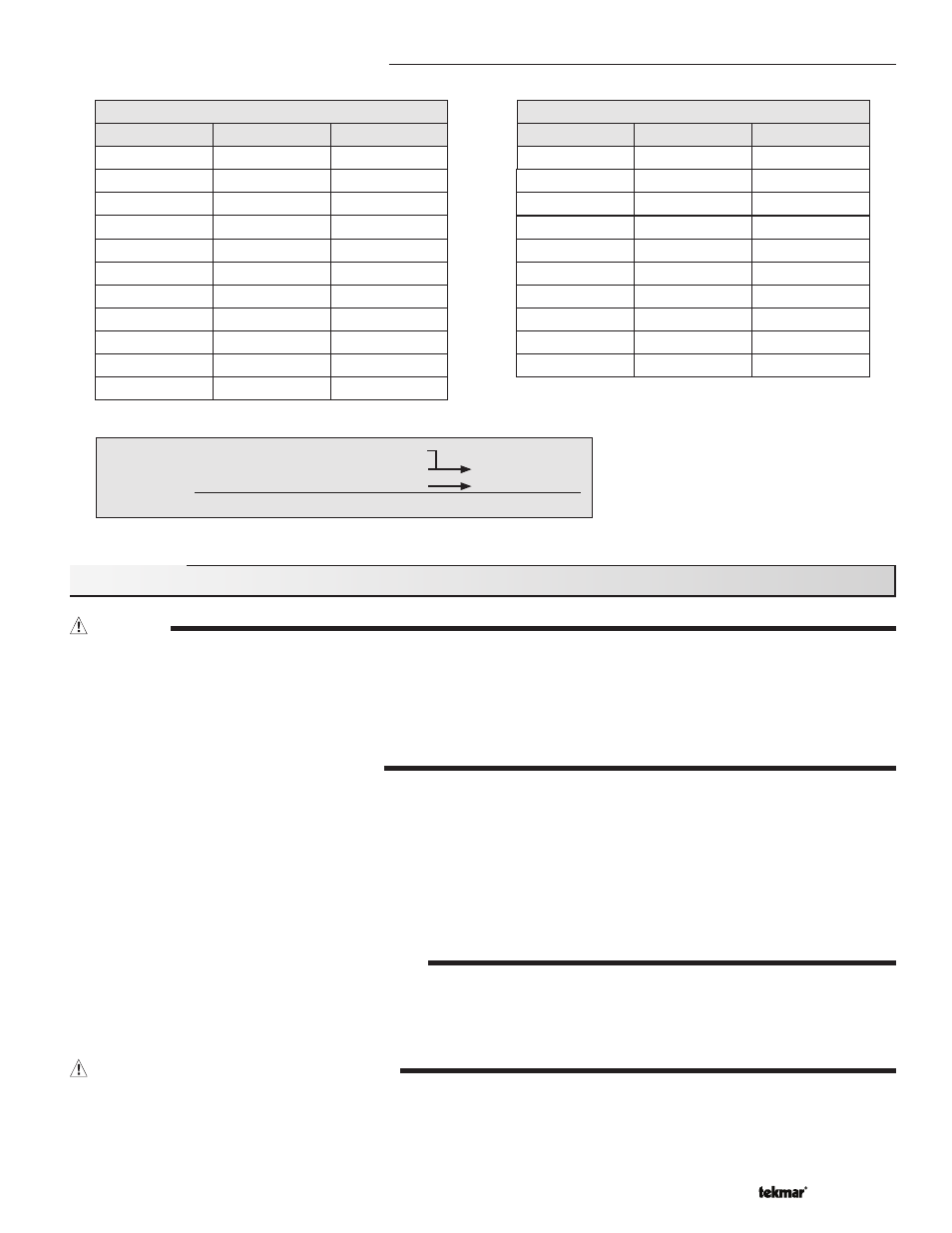
External Input Signal Conversion Tables
CAUTION
Improper installation and operation of this control could result in damage to the equipment and possibly even personal injury. It is
your responsibility to ensure that this control is safely installed according to all applicable codes and standards. This electronic
control is not intended for uses as a primary limit control. Other controls that are intended and certified as safety limits must be
placed into the control circuit. Do not open the control. Refer to qualified personnel for servicing. Opening voids warranty and could
result in damage to the equipment and possibly even personal injury.
STEP ONE
——————
GETTING READY
Check the contents of this package. If any of the contents listed are missing or damaged, please contact your wholesaler or tekmar
sales representative for assistance.
Type 268 includes: One Boiler Control 268, One Outdoor Sensor 070, Two Universal Sensors 082, Data Brochures D 268, D 070,
D 001, Application Brochure A 268
Note: Carefully read the details of the Sequence of Operation to ensure that you have chosen the proper control for
your application.
STEP TWO
——————
MOUNTING THE BASE
Remove the control from its base by pressing down on the release clip in the wiring chamber and sliding the control away from it.
The base is then mounted in accordance with the instructions in the Data Brochure D 001.
STEP THREE
————
ROUGH-IN WIRING
All electrical wiring terminates in the control base wiring chamber. The base has standard
7
/
8
” (22 mm) knockouts which accept
common wiring hardware and conduit fittings. Before removing the knockouts, check the wiring diagram and select those sections
of the chamber with common voltages. Do not allow the wiring to cross between sections as the wires will interfere with safety
dividers which should be installed at a later time.
CONVERSION TABLE 0 - 10
0 - 20 mA*
0
2
0 - 10 V (dc)
0
1
Boiler Target
– – – (OFF)
50°F (10°C)
4
2
68°F (20°C)
6
3
86°F (30°C)
8
4
103°F (39°C)
10
5
121°F (49°C)
12
6
139°F (59°C)
14
7
157°F (69°C)
16
8
174°F (79°C)
18
9
192°F (89°C)
20
10
210°F (99°C)
*Requires 500 Ω Resistor in Parallel
CONVERSION TABLE 2 - 10
4 - 20 mA*
0
2 - 10 V (dc)
0
Boiler Target
– – – (OFF)
4
2
50°F (10°C)
6
3
70°F (21°C)
8
4
90°F (32°C)
10
5
110°F (43°C)
12
6
130°F (54°C)
14
7
150°F (66°C)
16
8
170°F (77°C)
18
9
190°F (88°C)
20
10
210°F (99°C)
*Requires 500 Ω Resistor in Parallel
Installation
Example
Range
=
0 - 10 V (dc)
Input
=
7 V (dc)
157°F (69°C)
Offset
=
+5°F
(3°C) +
5°F (3°C)
Boiler Target =
162°F (72°C)