tekmar 268 Boiler Control User Manual
Page 18
© 2010
D 268 - 11/10
18 of 32
Power must not be applied to any of the wires during the rough-in wiring stage.
•
All wires are to be stripped to a length of
3
/
8
” (9 mm) to ensure proper connection to the control.
•
If an Outdoor Sensor 070 is used, install the sensor according to the installation instructions in the Data Brochure D 070 and run
the wiring back to the control.
•
Install the Boiler Supply Sensor 082 according to the installation instructions in the Data Brochure D 070 and run the wiring back
to the control.
•
If a Boiler Return Sensor 082 is used, install the sensor according to the installation instructions in the Data Brochure D 070 and
run the wiring back to the control.
•
Run wire from other system components (pumps, boilers, etc.) to the control.
•
Run wires from the 115 V (ac) power to the control. Use a clean power source with a 15 A circuit to ensure proper operation.
Multi-strand 16 AWG wire is recommended for all 115 V (ac) wiring due to its superior flexibility and ease of installation into
the terminals.
STEP FOUR
——————
ELECTRICAL CONNECTIONS TO THE CONTROL
General
The installer should test to confirm that no voltage is present at any of the wires. Push the control into the base and slide it down
until it snaps firmly into place.
9
10
115 V (ac)
N
L
Power
N
L
6
7
Boil
Dem
Com
Dem
24 to 230 V (ac)
7
Com
Dem
8
Setp/
DHW
24 to 230 V (ac)
1
Com
–
2
Do Not Apply Powe
r
Boil
Sup
3
Boil
Ret
4
Out
+
1
Com
–
2
Do Not Apply Powe
r
Boil
Sup
3
Boil
Ret
4
Out
+
0 - 10 V (dc)
or
2 - 10 V (dc)
0 - 20 mA
or
4 - 20 mA
500 Ω
–
+
–
+
Powered Input Connections
115 V (ac) Power
Connect the 115 V (ac) power supply to the Power L and Power N terminals (10 and 9).
This connection provides power to the microprocessor and display of the control. As
well, this connection provides power to the Prim P1 terminal (11) from the Power L
terminal (10).
Boiler Demand
To generate a boiler demand, a voltage between 24 V (ac) and 230 V (ac) must be
applied across the Boil Dem and Com Dem terminals (6 and 7).
DHW Demand
To generate a DHW Demand, a voltage between 24 V (ac) and 230 V (ac) must be
applied across the Setp / DHW and Com Dem terminals (8 and 7). If using DHW, the
last boiler in MODE 1, 4 or 5 must be set to OFF and DHW MODE must also be set
to 1 through 4.
Setpoint Demand
To generate a setpoint demand, a voltage between 24 V (ac) and 230 V (ac) must be
applied across the Setp / DHW and Com Dem terminals (8 and 7). The DHW MODE
must be set to OFF.
External Input
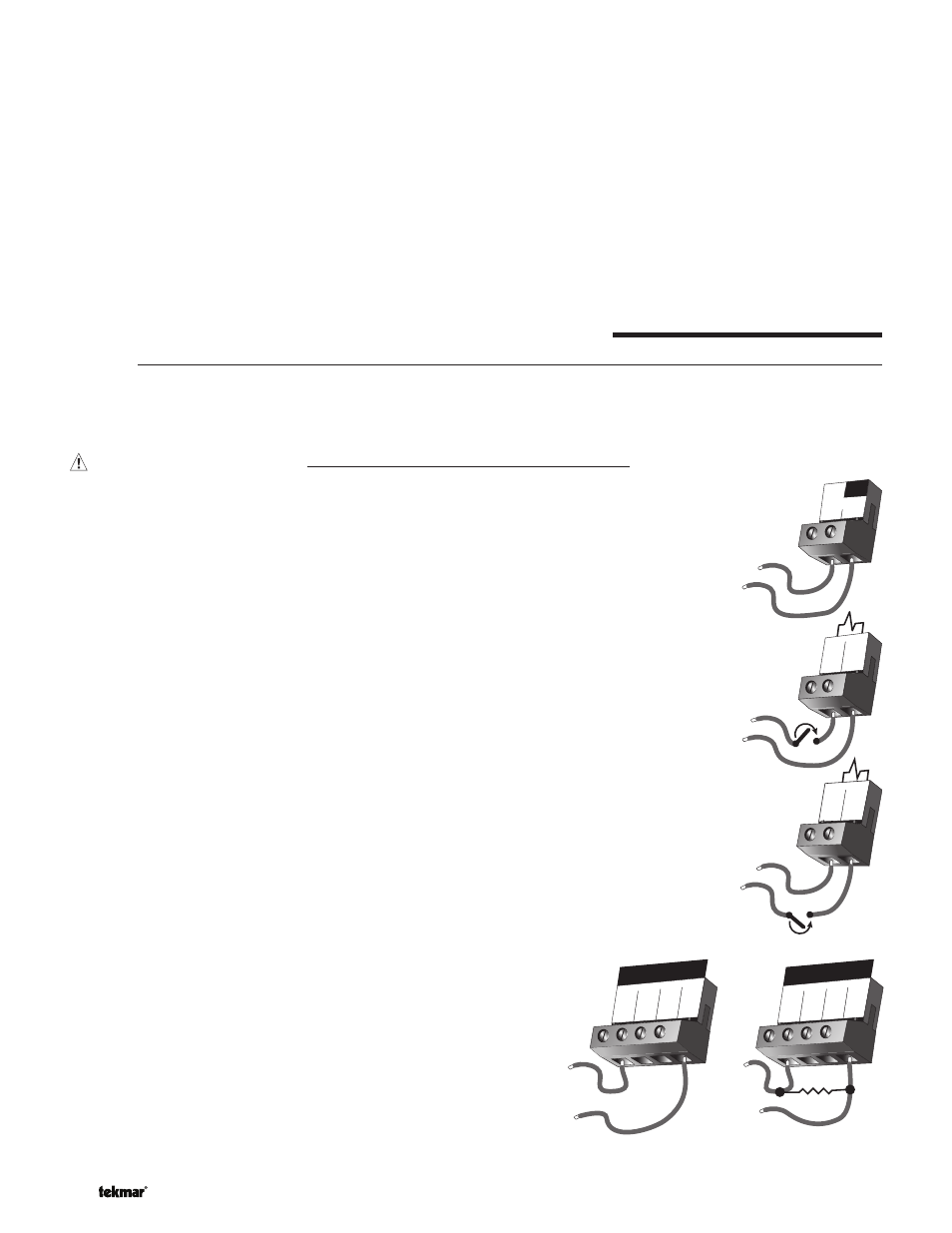
(0 - 10 V dc)
To generate an external input signal, a voltage between 0 and 10 V (dc)
must be applied to the Com – and Out + terminals (1 and 4).
A 0 - 20 mA signal can be converted to a 0 - 10 V (dc) signal by installing
a 500 Ω resistor between the Com – and Out + terminals (1 and 4).
A 4 - 20 mA signal can be converted to a 2 - 10 V (dc) signal by installing
a 500 Ω resistor between the Com – and Out + terminals (1 and 4).