tekmar 268 Boiler Control User Manual
Page 19
19 of 32
© 2010
D 268 - 11/10
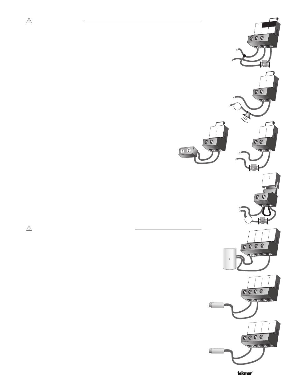
Output Connections
Primary Pump Contact
(Prim P1)
The Prim P1 output terminal (11) is a powered output. When the relay in the control
closes, 115 V (ac) is provided to the Prim P1 terminal (11) from the Power L terminal (10).
To operate the primary pump, connect one side of the primary pump circuit to
terminal 11 and the second side of the pump circuit to the neutral (N) side of the
115 V (ac) power supply.
Prim
P1
11
10
Power
N
L
9
L
N
115 V (ac)
12 13
24 to 230 V (ac)
C.A./
Alert
L
N
M
OR
Relay
15
14
1
1
Relay
15
14
1
1
24 to 230 V (ac)
L
N
OR
Boiler
1
Com
2
Boil
Sup
3
Boil
Ret
4
Out
Sensor and Unpowered Input Connections
Do not apply power to these terminals as this will damage the control.
2
1
3
4
Com Boil
Sup
Boil
Ret
Out
2
1
3
4
Com
Boil
Sup
Boil
Ret
Out
Relay 1 to Relay 9
The Relay 1 to Relay 9 terminals (14 and 15 to 30 and 31) are
isolated outputs in the control. There is no power available on these
terminals from the control. These terminals are to be used as a
switch to either make or break power to a boiler stage or a boiler
pump. Since this is an isolated contact, it may switch a voltage
between 24 V (ac) and 230 V (ac).
Combustion Air / Alert Contact
(C.A./Alert)
The Combustion Air / Alert Contact (C.A./Alert) terminals (12 and 13) are an isolated
output in the control. There is no power available on these terminals from the control.
These terminals are to be used as a switch to either make or break power to the
combustion air damper or alert. Since this is an isolated contact, it may switch a
voltage between 24 V (ac) and 230 V (ac).
Outdoor Sensor
If an outdoor sensor is used, connect the two wires from the Outdoor Sensor 070 to
the Com – and Out + terminals (1 and 4). The outdoor sensor is used by the control to
measure the outdoor air temperature.
Boiler Supply Sensor
Connect the two wires from the Boiler Supply Sensor 082 to the Com – and Boil Sup
terminals (1 and 2). The boiler supply sensor is used by the control to measure the
boiler supply water temperature.
Boiler Return Sensor
If a boiler return sensor is used, connect the two wires from the Boiler Return Sensor
082 to the Com – and Boil Ret terminals (1 and 3). The boiler return sensor is used by
the control to measure the boiler return water temperature.
Relay 9 / DHW
If a DHW pump or DHW valve is connected to the Relay 9 / DHW contact (30 and 31),
make sure the power to the pump or valve circuit is off and install a jumper between
those terminals. When the DHW circuit is powered up, the DHW pump should turn on
or the DHW valve should open completely. If the DHW pump or valve fails to operate,
check the wiring between the terminals and the pump or valve and refer to any instal-
lation or troubleshooting information supplied with these devices. If the DHW pump or
valve operates correctly, disconnect the power and remove the jumper.
31
30
Relay 9/
DHW
24 to 230 V (ac)
L
N
M
OR