tekmar 264 Boiler Control User Manual
Page 4
©
2008 D
264
-
12/08
4
of
32
Section A
General
Operation
Page 4 - 6
Section B
Staging
Operation
Page 6 - 8
Section C
Pump
Operation
Page 8 - 9
Section D
Boiler Reset
Operation
Page 9 - 11
POWERING UP THE CONTROL
When the control is powered up, all segments in the LCD are turned on for 2 seconds. Next, the control displays the control type
number in the LCD for 2 seconds. Next, the software version is displayed for 2 seconds. Finally, the control enters into the normal
operating mode.
OPERATION
The control operates up to four on / off heat sources to control the supply water temperature to a hydronic system. The supply water
temperature is based on either the current outdoor temperature or a fixed setpoint.
Section E
DHW
Operation
Page 12 - 14
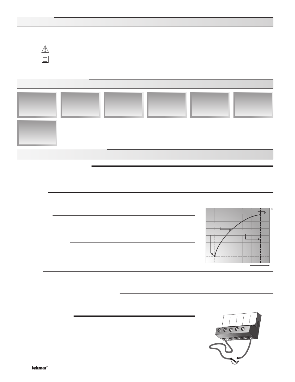
Decreasing Outdoor Temperature
Incr
easing W
a
ter T
e
mperatur
e
Terminal Unit
Terminal Unit
Indoor Design
Indoor Design
Outdoor Design
Outdoor Design
Design Supply
Design Supply
1
Com
2
Boil
Sup
3
Boil
Ret
4
Out
5
UnO
Sw
Timer Switch
The following defined terms and symbols are used throughout this manual to bring attention to the presence of hazards of various risk
levels, or to important information concerning the life of the product.
INSTALLATION
CATEGORY II
- Warning Symbol: Indicates presence of hazards which can cause severe personal injury, death or
substantial property damage if ignored.
- Double
insulated
- Local level, appliances
Definitions
Sequence Of Operation
Section A: General Operation
Section F
Setpoint
Operation
Page 15 - 15
Boiler Reset
When a boiler demand signal from the heating system is present, the control operates
the boiler(s) to maintain a supply temperature based on the outdoor air temperature and
Characterized Heating Curve settings.
Domestic Hot Water
When a DHW demand signal from a DHW aquastat is present, the control operates the
boiler(s) to maintain the supply water temperature at least as hot as the DHW XCHG setting.
Refer to section E.
SETBACK
(UNOCCUPIED)
To provide greater energy savings, the control has a setback feature. With setback, the
supply water temperature in the system is reduced when the building is unoccupied. By
reducing the supply water temperature, the air temperature in the space may be reduced
even when a thermostat is not turned down. Any time the UnO Sw (5) and the Com (1) are
shorted together, the control operates in the UnOccupied mode. When in the UnOccupied
mode, the UNOCC segment is displayed in the LCD. The control adjusts the supply water
temperature based on the UNOCC settings made in the control.
Setpoint
When a setpoint demand signal from a setpoint system is present, the control operates the boiler(s) to maintain the supply water
temperature at least as hot as the SETP setting. Refer to section F.
External Input 0 - 10 V (dc) or 2 - 10 V (dc)
When an external input signal is present, the control converts the signal to a target supply temperature. The control operates the
boiler(s) to maintain the required supply water temperature.
Section G
External Input
Operation
Page 16 - 17