tekmar 264 Boiler Control User Manual
Page 19
19 of 32
© 2008 D 264 - 12/08
Prim
P1
11
10
Power
N
L
9
L
N
115 V (ac)
12 13
24 to 230 V (ac)
C.A./
Alarm
L
N
M
OR
1
Com
2
Boil
Sup
3
Boil
Ret
4
Out
2
1
3
4
Com Boil
Sup
Boil
Ret
Out
Relay
15
14
1
1
Relay
15
14
1
1
24 to 230 V (ac)
L
N
OR
Boiler
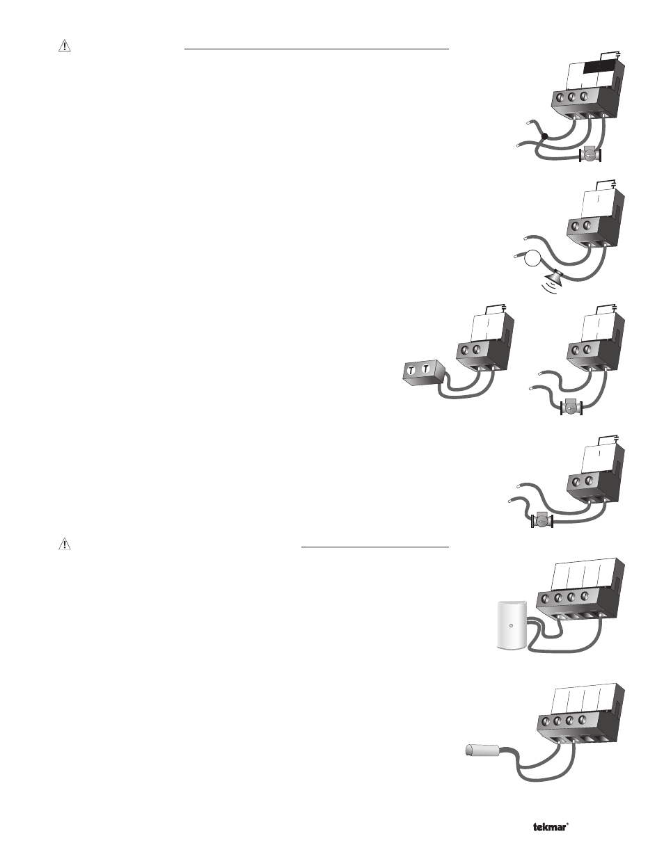
Relay 1 to Relay 4
The Relay 1 to Relay 4 terminals (14 and 15 to 20 and 21) are
isolated outputs in the control. There is no power available on these
terminals from the control. These terminals are to be used as a
switch to either make or break power to a boiler stage or a boiler
pump. Since this is an isolated contact, it may switch a voltage
between 24 V (ac) and 230 V (ac).
Sensor and Unpowered Input Connections
Do not apply power to these terminals as this will damage the control.
Outdoor Sensor
Connect the two wires from the Outdoor Sensor 070 to the Com and Out terminals
(1 and 4). The outdoor sensor is used by the control to measure the outdoor air
temperature.
Boiler Supply Sensor
Connect the two wires from the Boiler Supply Sensor 071 to the Com and Boil Sup
terminals (1 and 2). The boiler supply sensor is used by the control to measure the
boiler supply water temperature.
DHW Pmp / Vlv
The DHW Pmp / Vlv terminals (22 and 23) are isolated outputs in the control. There
is no power available on these terminals from the control. These terminals are to be
used as a switch to either make or break power to a DHW pump or valve. Since this is
an isolated contact, it may switch a voltage between 24 V (ac) and 230 V (ac).
22 23
DHW
Pmp/Vlv
24 to 230 V (ac)
Output Connections
Primary Pump Contact
(Prim P1)
The Prim P1 output terminal (11) is a powered output. When the relay in the control
closes, 115 V (ac) is provided to the Prim P1 terminal (11) from the Power L terminal (10).
To operate the primary pump, connect one side of the primary pump circuit to
terminal 11 and the second side of the pump circuit to the neutral (N) side of the
115 V (ac) power supply.
Combustion Air / Alarm Contact
(C.A. / Alarm)
The Combustion Air / Alarm Contact (C.A. / Alarm) terminals (12 and 13) are an
isolated output in the control. There is no power available on these terminals from the
control. These terminals are to be used as a switch to either make or break power to
the combustion air damper or alarm. Since this is an isolated contact, it may switch a
voltage between 24 V (ac) and 230 V (ac).