tekmar 264 Boiler Control User Manual
Page 18
©
2008 D
264
-
12/08
18
of
32
STEP THREE
————
ROUGH-IN WIRING
All electrical wiring terminates in the control base wiring chamber. The base has standard
7
/
8
” (22 mm) knockouts which accept
common wiring hardware and conduit fittings. Before removing the knockouts, check the wiring diagram and select those sections
of the chamber with common voltages. Do not allow the wiring to cross between sections as the wires will interfere with safety
dividers which should be installed at a later time.
Power must not be applied to any of the wires during the rough-in wiring stage.
•
All wires are to be stripped to a length of
3
/
8
” (9 mm) to ensure proper connection to the control.
•
If an Outdoor Sensor 070 is used, install the sensor according to the installation instructions in the Data Brochure D 070 and run
the wiring back to the control.
•
Install the Boiler Supply Sensor 071 according to the installation instructions in the Data Brochure D 070 and run the wiring back
to the control.
•
If a Boiler Return Sensor 071 is used, install the sensor according to the installation instructions in the Data Brochure D 070 and
run the wiring back to the control.
•
Run wire from other system components (pumps, boilers, etc.) to the control.
•
Run wires from the 115 V (ac) power to the control. Use a clean power source with a 15 A circuit to ensure proper operation.
Multi-strand 16 AWG wire is recommended for all 115 V (ac) wiring due to its superior flexibility and ease of installation into
the terminals.
9
10
115 V (ac)
N
L
Power
N
L
6
7
Boil
Dem
Com
Dem
24 to 230 V (ac)
STEP FOUR
——————
ELECTRICAL CONNECTIONS TO THE CONTROL
General
The installer should test to confirm that no voltage is present at any of the wires. Push the control into the base and slide it down
until it snaps firmly into place.
Powered Input Connections
115 V (ac) Power
Connect the 115 V (ac) power supply to the Power L and Power N terminals (10 and 9).
This connection provides power to the microprocessor and display of the control. As
well, this connection provides power to the Prim P1 terminal (11) from the Power L
terminal (10).
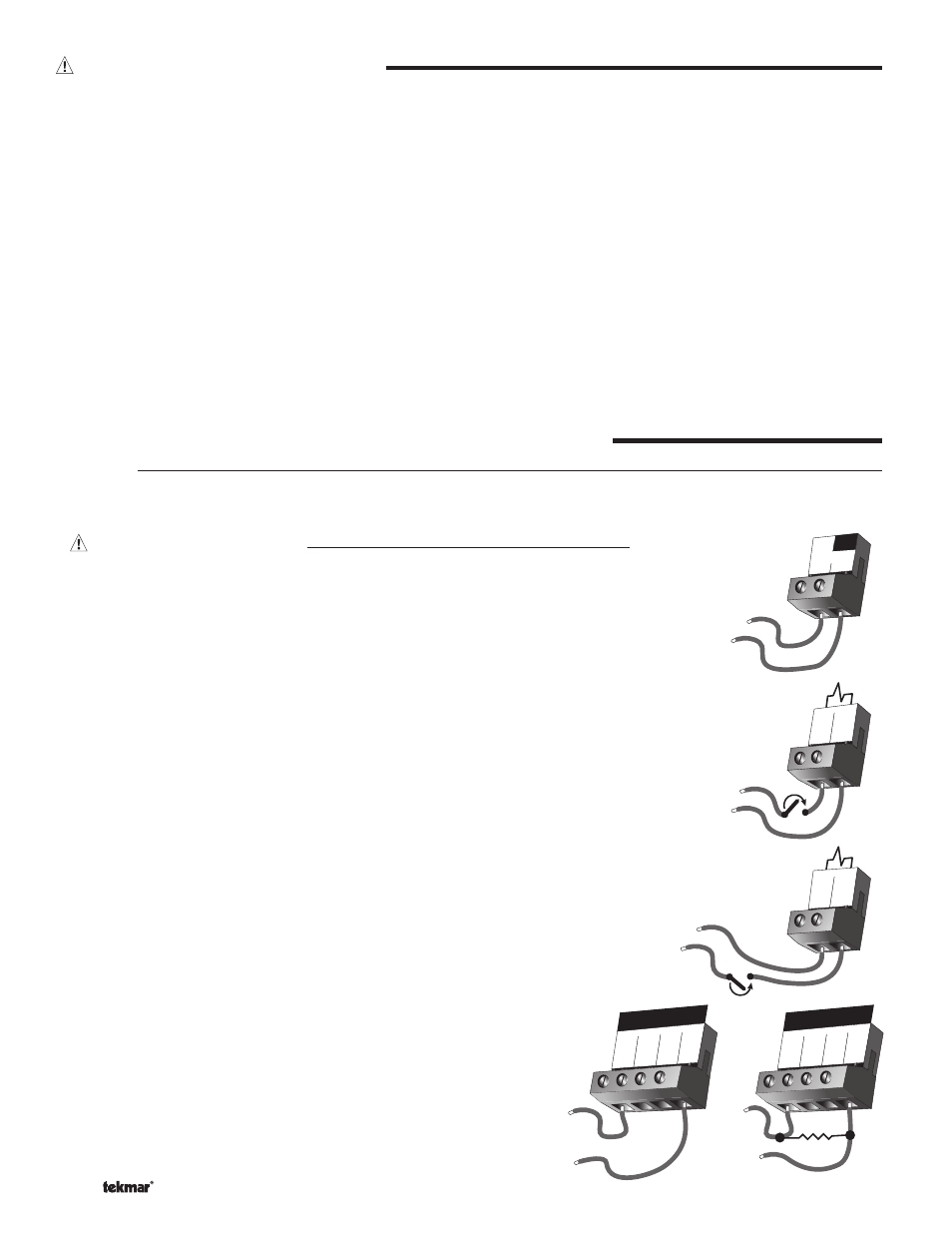
Boiler Demand
To generate a boiler demand, a voltage between 24 V (ac) and 230 V (ac) must be
applied across the Boil Dem and Com Dem terminals (6 and 7).
DHW Demand
If a DHW demand is used, measure the voltage between the Setp / DHW and the
Com Dem terminals (8 and 7). When the DHW demand device calls for heat, a volt-
age between 20 and 260 V (ac) should be measured at the terminals. When the DHW
demand device is off, less than 5 V (ac) should be measured.
Setpoint Demand
If a setpoint demand is used, measure the voltage between the Setp / DHW and
the Com Dem terminals (8 and 7). When the setpoint demand device calls for heat,
you should measure between 20 and 260 V (ac) at the terminals. When the setpoint
demand device is off, you should measure less than 5 V (ac).
7
8
Com
Dem
Setp/
DHW
24 to 230 V (ac)
1
Com
–
2
Do Not Apply Powe
r
Boil
Sup
3
Boil
Ret
4
Out
+
1
Com
–
2
Do Not Apply Powe
r
Boil
Sup
3
Boil
Ret
4
Out
+
0 - 10 V (dc)
or
2 - 10 V (dc)
0 - 20 mA
or
4 - 20 mA
500 Ω
–
+
–
+
External Input
(0 - 10 V dc)
To generate an external input signal, a voltage between 0 and 10 V (dc)
must be applied to the Com – and Out + terminals (1 and 4).
A 0 - 20 mA signal can be converted to a 0 - 10 V (dc) signal by installing
a 500 Ω resistor between the Com – and Out + terminals (1 and 4).
A 4 - 20 mA signal can be converted to a 2 - 10 V (dc) signal by installing
a 500 Ω resistor between the Com – and Out + terminals (1 and 4).