tekmar 264 Boiler Control User Manual
Page 22
©
2008 D
264
-
12/08
22
of
32
9
Power
L
N
Prim
P1
10 11
L
N
15
14
Relay
1
1
15
14
Relay
1
1
24 to 230 V (ac)
L
N
13
12
C.A./
Alarm
M
24 to 230 V (ac)
L
N
OR
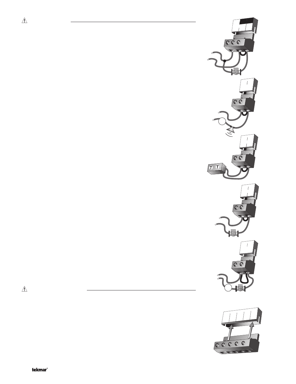
Test The Outputs
Primary Pump
(Prim P1)
If a primary pump is connected to the Prim P1 terminal (11), make sure that power
to the terminal block is off and install a jumper between the Power L and Prim P1
terminals (10 and 11). When power is applied to the Power N and Power L terminals
(9 and 10), the primary pump should start. If the pump does not turn on, check the wiring
between the terminal block and pump and refer to any installation or troubleshooting
information supplied with the pump. If the pump operates properly, disconnect the
power and remove the jumper.
Combustion Air or Alarm
(C.A. / Alarm)
If a combustion air damper or an alarm is connected to the C.A. / Alarm termi-
nals (12 and 13), make sure power to the damper or alarm circuit is off and install a
jumper between terminals (12 and 13). When the circuit is powered up, the combustion
air damper should open or the alarm should activate. If the damper or the alarm fails
to operate, check the wiring between the terminals and the damper or the alarm and
refer to any installation or troubleshooting information supplied with these devices. If
the damper or the alarm operates properly, disconnect the power and remove the
jumper.
Relay 1 to Relay 4
The Relay 1 to Relay 4 terminals (14 and 15 to 20 and 21) are isolated outputs in
the control. There is no power available on these terminals from the control. These
terminals are to be used as a switch to either make or break power to a boiler stage or
a boiler pump. Since this is an isolated contact, it may switch a voltage between 24 V
(ac) and 230 V (ac).
If a boiler pump is connected to the Relay 1 terminals (14 and 15), make sure that
power to the terminal block is off and install a jumper between the terminals. When
power is applied to circuit, the boiler pump should start. If the pump does not turn on,
check the wiring between the terminal block and pump and refer to any installation or
troubleshooting information supplied with the pump. If the pump operates properly,
disconnect the power and remove the jumper.
Repeat the above procedure for Relay 2 to Relay 4.
DHW Pmp / Vlv
If a DHW pump or DHW valve is connected to the DHW Pmp / Vlv contact (22 and 23),
make sure the power to the pump or valve circuit is off and install a jumper between
those terminals. When the DHW circuit is powered up, the DHW pump should turn on
or the DHW valve should open completely. If the DHW pump or valve fails to operate,
check the wiring between the terminals and the pump or valve and refer to any instal-
lation or troubleshooting information supplied with these devices. If the DHW pump or
valve operates correctly, disconnect the power and remove the jumper.
Connecting The Control
Make sure all power to the devices and terminal blocks is off, and remove any remaining
jumpers from the terminals.
Reconnect the terminal blocks to the control by carefully aligning them with their
respective headers on the control, and then pushing the terminal blocks into the headers.
The terminal blocks should snap firmly into place.
Install the supplied safety dividers between the unpowered sensor inputs and the
powered or 115 V (ac) wiring chambers.
Apply power to the control. The operation of the control on power up is described in the
Sequence of Operation section of the brochure.
23
22
DHW
Pmp/Vlv
24 to 230 V (ac)
L
N
M
OR
1 2 3
4
Com
Boil
Ret
Out
5
UnO
Sw
Boil
Sup