Landing gear installation – E-flite Cessna 150 Aerobat 250 ARF User Manual
Page 10
10
E-flite Cessna 150 Aerobat 250 ARF Assembly Manual
Landing Gear Installation
Required parts
Fuselage assembly Steering arm
Nose gear wire
Main landing gear
2mm nut (2)
2mm washer (4)
Wood spacer (3)
Nose wheel pant
3mm washer (2)
Main wheel pant (2)
Wheel collar with setscrew(3)
2mm x 25mm machine screw (2)
Pushrod connector with hardware
Main wheel, 1.57-inch (40mm) (2)
Nose wheel, 1.37-inch (35mm)
3mm x 8mm self-tapping screw (2)
Required Tools and Adhesives
Flat file
Phillips screwdriver: #1, #2
Hex wrench: 1.5mm Hemostat
Canopy glue
Low-tack tape
Threadlock
Medium CA
Toothpick
Pin vise
Ruler
Drill bit: 5/64-inch (2mm)
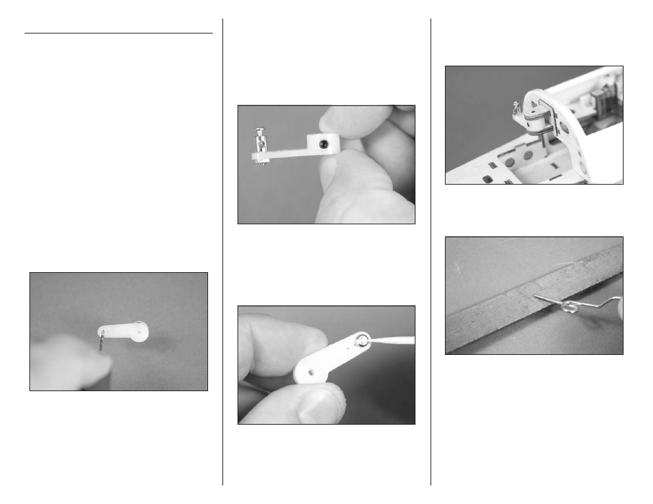
1. Use a pin vise and 5/64-inch (2mm) drill bit to
enlarge the outer hole in the steering arm.
2. Attach the pushrod connector to the outside hole
of the steering arm as shown. The washers that
come on the connector are not needed and can
be removed. Tighten the nut so it is secure on the
steering arm but is not tight. There should be a small
amount of play between the arm and the connector
and the connector should be able to rotate freely on
the arm.
3. Use a very small amount of medium CA on a
toothpick to secure the nut to the bottom of the
connector threads. Do not use thin CA for this
step as it can wick through the nut and glue the
connector to the arm. Make sure that the connector
still rotates freely in the arm after the glue is cured.
4. Install the steering arm into the bracket on the
lower section of the fire wall. The steering arm will fit
in the bracket as shown with the pushrod connector
facing the bottom of the fuselage.
5. The end of the nose gear wire may have to
be filed slightly to remove any burs or edges for
an easier fit.