Carbon bracing installation – E-flite 4-Site F3P 250 ARF User Manual
Page 9
9
E-flite 4-Site Assembly Manual
Carbon Bracing Installation
Required Parts
Airframe assembly
12
3
/
4
x 1/32-inch (325mm x 1mm) carbon rod,
Main wing bracing (4)
4
1
/
8
x 1/32-inch (105mm x 1mm) carbon rod,
Outer strut to tip bracing (4)
5
5
/
16
x 1/32-inch (135mm x 1mm) carbon rod,
Top wing to fuselage bracing (2)
5
3
/
4
x 1/32-inch (145mm x 1mm) carbon rod,
Horizontal tail to fuselage bracing (2)
Required Tools and Adhesives
Square
Foam-safe CA
T-pin
When installing the carbon rods, twisting them with
your fingers while inserting them in the hole will help
to smooth the exit and entry of the carbon rod.
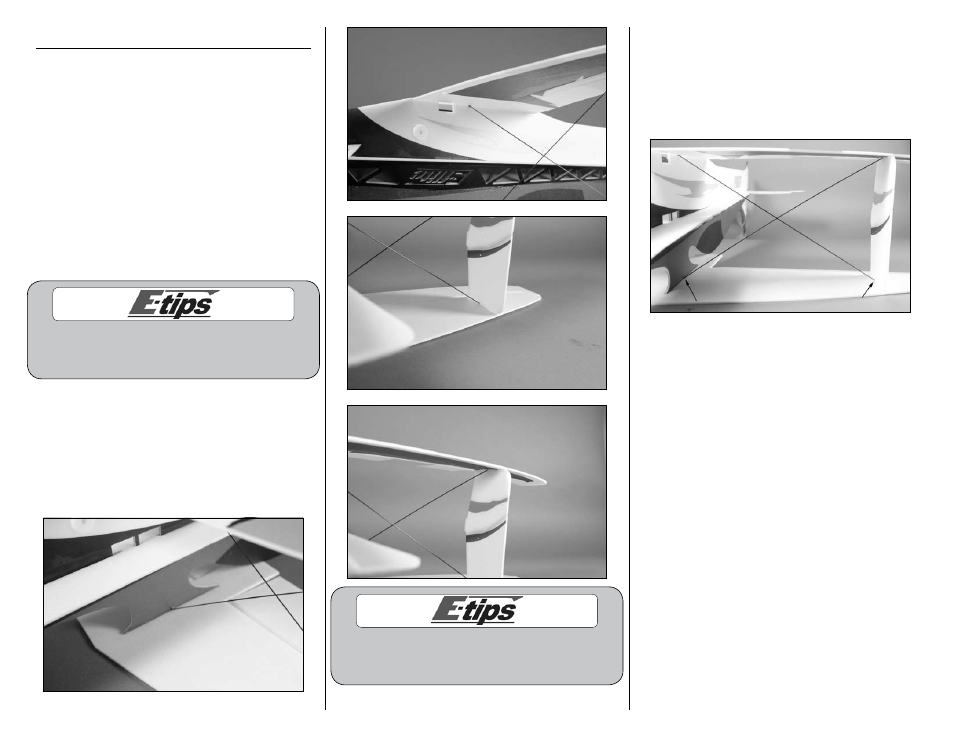
1. Use the following images to position the four
pieces of 12
3
/
4
x 1/32-inch (325mm x 1mm)
carbon rod (two pieces on either side of the
fuselage) that keep the top and bottom wings in
alignment with the fuselage. Do not apply CA until
instructed. The rod that runs from the top of the
center cabane to the lower outer strut should be on
the front of the cross.
When positioning the fuselage upside down on your
work surface, the fin will need to hang off the edge of
your work surface to keep the top wing perfectly flat.
2. With the top wing flat on your work surface,
check that the struts and fuselage are square to the
top and bottom wings. Apply a small amount of
foam-safe CA at the points where the carbon rod
are inserted in the top wing. The rod should be
inserted completely through the wing but should not
protrude past the top of the wing.
3. Make sure to keep the airframe very square
while proceeding. Apply a few drops of foam-safe
CA to the carbon rods where they enter the bottom
wing. Also apply CA to the junction between the
carbon rods where they cross each other. You can
trim off any excess rod from the bottom of the wing
after all four rods have been glued at each joint.