Control horn installation – E-flite 4-Site F3P 250 ARF User Manual
Page 14
14
E-flite 4-Site Assembly Manual
6. Use a #1 Phillips screwdriver and the two screws
provided with your motor to attach it to the firewall.
Work slowly to avoid applying too much pressure,
resulting in damage to your airframe.
7. Pass the motor wires through the slot in the front
of the fuselage. Connect the wires from the motor
to those of the speed control. The battery lead
from the speed control can now be passed to the
opposite side of the fuselage through the slot in the
fuselage as well.
8. Check the operation of the motor at this time.
It should rotate counterclockwise when viewed
from the front of the aircraft. If not, follow the
instructions provided with your speed control to
correct the situation.
Never check the motor rotation on the bench
with the propeller installed. The plane could
move and cause serious injury. Always check the
motor without the propeller to avoid injury.
9. Use foam-safe CA to glue the right lower
diagonal brace on the fuselage.
10. The speed control should be positioned
between the two braces as shown.
Control Horn Installation
Required Parts
Assembled airframe Depron control horn support
(4)
13/16 x 1/16-inch (20mm x 1mm) carbon rod,
control rod (4)
Required Tools and Adhesives
Foam-safe CA
Hobby knife
Felt-tipped pen
Low-tack tape
Ruler
T-pin
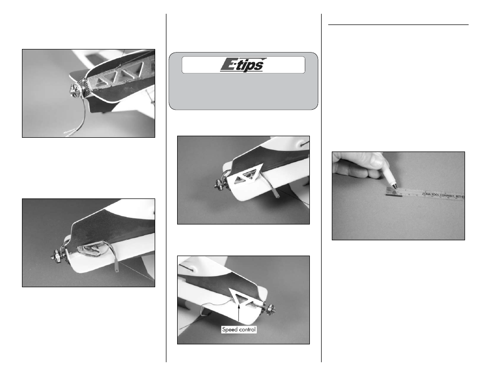
1. Use a ruler and felt-tipped pen to measure
and mark the four 13/16 x 1/16-inch (20mm
x 1mm) carbon rods 19/32-inch (15mm) from
the end of each rod.