E-flite 4-Site F3P 250 ARF User Manual
Page 18
18
E-flite 4-Site Assembly Manual
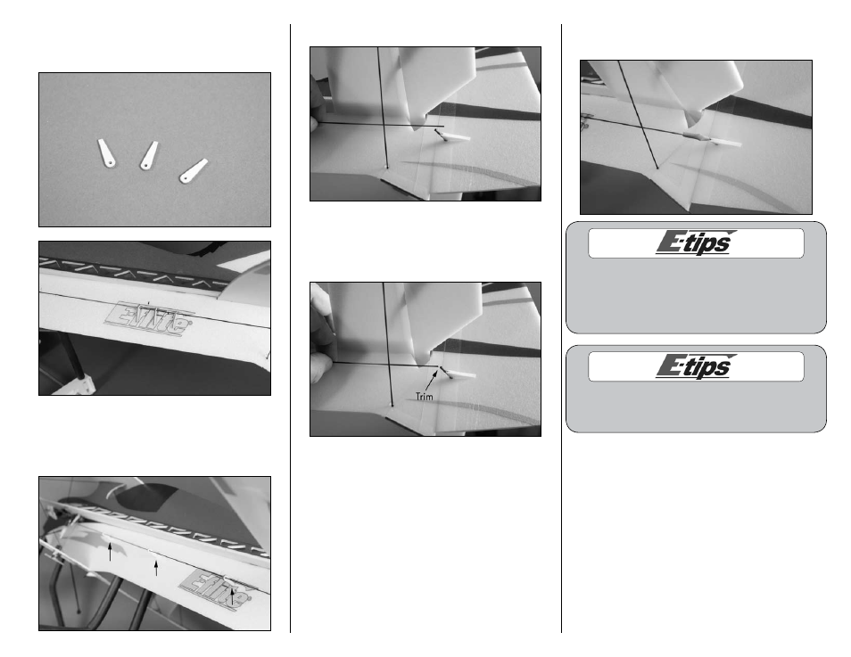
9. Locate three of the pushrod supports and slide
the supports onto the pushrod as shown in the
second photo.
10. Insert the pushrod guides into the slots in the
fuselage. In each position, there is a pair of holes.
The rudder pushrod supports go in the rear hole of
each pair. Do not glue the supports yet.
11. Align the pushrod with the rudder control horn.
12. The pushrod is supplied slightly long to
accommodate for servo selection and control horn
position. Use side cutters to trim the pushrod so it
almost touches the rudder control horn.
13. Slide a piece of heat shrink on the pushrod
and control horn.
Only use a soldering iron to shrink the
tubing for the control rods. A heat gun or
lighter will damage the control surfaces.
Use care not to touch the soldering iron
to any of the control surfaces.
You will notice that there is extra heat shrink
supplied with the kit. This is in case you
lose one or need to redo a linkage.
- Habu 32x DF ARF (84 pages)
- A6M5 Zero 300 BNF Basic (17 pages)
- Hawker Sea Fury 480 ARF (28 pages)
- Mystique RES 2.9m ARF (52 pages)
- Super Cub 25e ARF (48 pages)
- AT-6 Texan 25 ARF (52 pages)
- LR-1A Pogo ARF 15e (21 pages)
- J-3 Cub 450 (40 pages)
- Hawker Hurricane 25e PNP (26 pages)
- Hawker Hurricane 25e PNP addendum (1 page)
- Apprentice 15e PNP (28 pages)
- Sukhoi SU-26m 480 ARF (28 pages)
- Beechcraft Bonanza 15e ARF (60 pages)
- Byp Yak 3D ARF (40 pages)
- Ultimate Fx 3D ARF (40 pages)
- Tribute FX 3D ARF (28 pages)
- Sobre 3D Profile (32 pages)
- Ascent EP Park Glider ARF (23 pages)
- Float Set Complete: Carbon-Z Cub (2 pages)
- Carbon-Z Cub PNP (27 pages)
- Carbon-Z Cub PNP Addendum (1 page)
- BAe Hawk 15 DF ARF (36 pages)
- Edge 540QQ 280 BNF Basic (19 pages)
- P-40 Warhawk 300 ARF (20 pages)
- Hawker Sea Fury 400 ARF (40 pages)
- Clipped Wing Cub 250 ARF (40 pages)
- T-34 Mentor 25e ARF (28 pages)
- Ultra Stick 25e ARF (40 pages)
- Ultra Stick 25e ARF Programming Guide (5 pages)
- Slick 3D 480 ARF (48 pages)
- PT-19 450 ARF (44 pages)
- Extra 330SC BP 3D ARF (40 pages)
- Cap 232 BP ARF (44 pages)
- Brio 10 ARF (56 pages)
- Park 480 BL Motor Combo (4 pages)
- Mini Edge 3D ARF (44 pages)
- Cessna 182 370 ARF (32 pages)
- Cessna 182/Park 400 BL Motor Combo (4 pages)
- Tribute 3D Profile ARF (40 pages)
- Fokker DVII 250 ARF (28 pages)
- Enticement F3P ARF (36 pages)
- Carbon-Z Yak 54 3X BNF Basic (23 pages)
- Carbon-Z Scimitar PNP (28 pages)
- UMX B-17G Flying Fortress BNF (18 pages)
- UMX Sbach 342 3D BNF Basic (17 pages)