Radio and linkage installation – E-flite 4-Site F3P 250 ARF User Manual
Page 16
16
E-flite 4-Site Assembly Manual
Radio and Linkage Installation
Required Parts
Assembled airframe Transmitter
Receiver
Heat shrink (8)
Servo (3)
Receiver
3D Servo arm (3)
Hook and loop tape
23
5
/
8
-inch (600mm) rudder and elevator
carbon pushrod (2)
3
1
/
2
-inch (90mm) aileron carbon pushrod (2)
6
7
/
8
-inch (175mm) aileron link carbon rod (2)
1 x 3/32-inch (25mm x 2mm) carbon rod,
aileron control horn (4)
Required Tools and Adhesives
Foam-safe CA
Phillips screwdriver, #0
Soldering iron
Clear tape
Side cutters
Low-temperature glue gun
1. Plug the rudder, elevator and aileron servos into
their corresponding ports of the receiver. Starting
with a new model, turn on the radio to center the
servos. Use a #0 Phillips screwdriver to remove the
original arms from the servos and install the long
3D arms.
There are more ways to lighten the 4-Site. Some
of these options will void the warranty for the
products used. These steps are covered in the E-flite
Enticement manual which can be found on the
Enticement product page at www.horizonhobby.com.
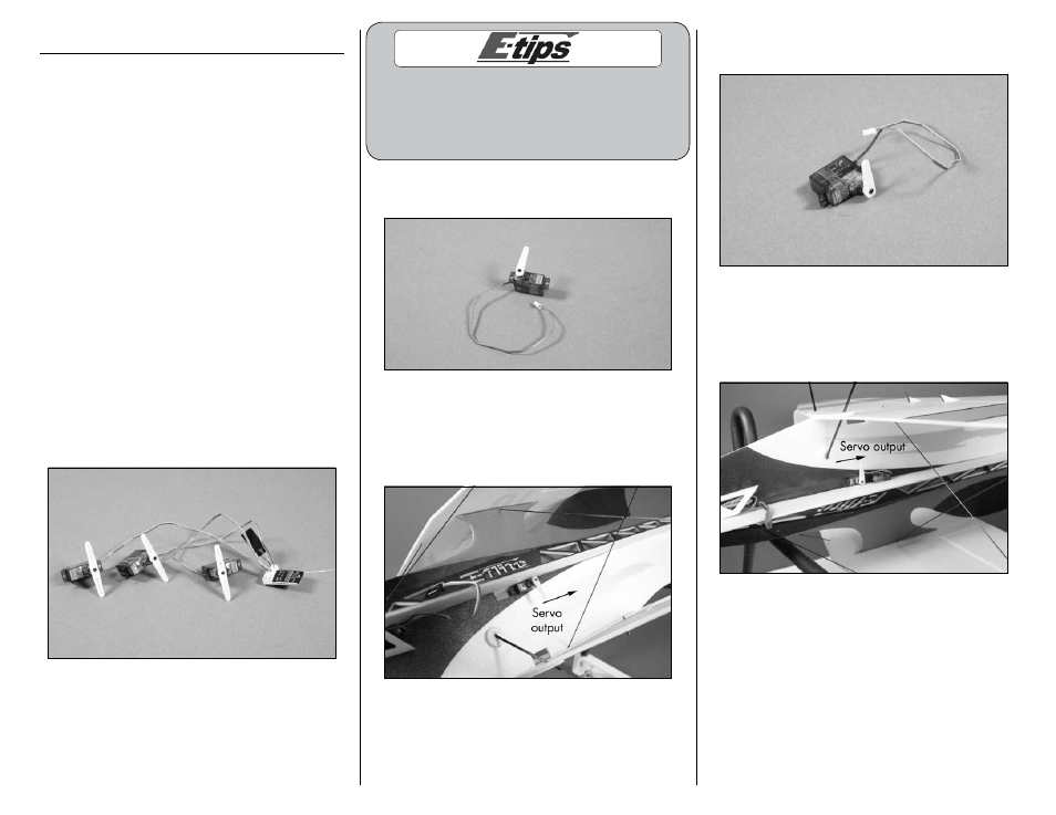
2. Prepare the rudder servo by removing the
unused arm from the servo horn as shown.
3. Test fit the rudder servo in the rear hole in the
main fuselage. The output of the servo will face the
tail of the aircraft. Once fit, use a low-temperature
glue gun or foam-safe CA to adhere the servo to
the fuselage.
4. Prepare the elevator servo by removing the
unused arm from the servo horn as shown.
5. Test fit the elevator servo in the remaining hole
in the main fuselage. The output of the servo will
face the tail of the aircraft. Once fit, use a low-
temperature glue gun or foam-safe CA to adhere
the servo to the fuselage.