Fixed gear installation – E-flite Hawker Sea Fury 480 ARF User Manual
Page 5
5
E-flite Hawker Sea Fury 480 ARF Assembly Manual
During the course of building your model, we
suggest you use a soft base for the building surface.
Such things as a foam stand, large piece of
bedding foam or a thick bath towel will work well
and help protect the model from damage during
assembly. This is not shown in the instructions
to provide the greatest detail in the photos.
When referencing directions (up, down, left,
right top and bottom), these directions are in
relationship to the pilot sitting in the cockpit
of the aircraft, unless noted otherwise.
Before starting the assembly of your model, we
recommend preparing your radio system for
installation. This includes charging the transmitter and
receiver batteries, as well as centering the trims and
sticks on your transmitter. If using a computer radio,
make sure to reset a model memory and name it for
this particular model. We also recommend binding
the transmitter and receiver at this time, following
the instructions provided with your radio system.
We highly recommend re-binding the radio
system once all the control throws are set. This will
keep the servos from moving to their endpoints
until the transmitter and receiver connect.
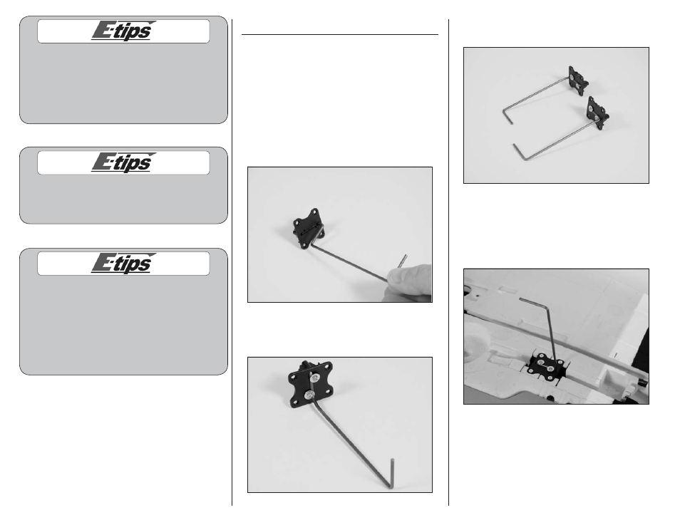
Fixed Gear Installation
Required parts
Fixed main gear wire (right and left)
Landing gear block (2)
2mm x 10mm shoulder screw (4)
3mm x 6mm countersunk sheet metal screw (8)
Required Tools and Adhesives
Phillips screwdriver: #0, #1
1. Insert the landing gear into the landing gear
block.
2. Use two 2mm x 10mm shoulder screws and a
#0 Phillips screwdriver to secure the landing gear
to the landing gear block.
3. Repeat Steps 1 and 2 to assemble the second
landing gear. (Make one left and one right)
4. Secure the landing gear assembly in the wing
using a #1 Phillips screwdriver and four 3mm x
6mm countersunk sheet metal screws per assembly.
The strut is positioned toward the wing tip and is
angled toward the leading edge when installed
correctly.