Msm series corner mirrors, Msm series construction, Alignment of sensors and corner mirrors – Banner MSM Series Corner Mirrors User Manual
Page 2
MSM Series Corner Mirrors
page
2
Banner Engineering Corp.
•
Minneapolis, U.S.A.
www.bannerengineering.com • Tel: 763.544.3164
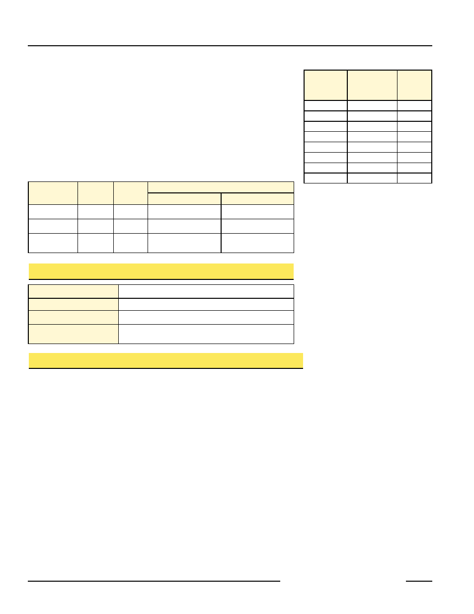
MSM Series mirrors may also be used with light screen sensors up to 48" long. The
table at right, recommends which mirror to use with the applicable sensors.
Each mirror is supplied with two mounting brackets and associated hardware (see
dimension drawing).
Mirrors should be securely mounted to a solid surface that is free from vibration.
Mirrors must be mounted parallel to their sensors, with the midpoint of the mirror(s)
directly in line with the midpoint of the sensor’s defined area.
MSA Series stands may be used to mount MSM Series mirrors. These stands offer an
extruded channel design for convenient mirror (or sensor) height adjustment. See
data sheet P/N 43687 for complete information. Several stand heights are available:
Light Screen
Defined Area
Length Up To
Recommended
Mirror Model
Reflective
Area
Length
8.5"
MSM8A
10.5"
12"
MSM12A
14"
18"
MSM20A
22"
24"
MSM24A
26"
30"
MSM32A
34"
36"
MSM36A
38"
42"
MSM44A
46"
48"
MSM48A
50"
Stand
Model
Part
Number
Stand
Height
Mirror Length
MSA-S24-1
43174
24"
4" to 8"
4" to 12"
MSA-S42-1
43175
42"
4" to 24"
4" to 28"
MSA-S66-1
43176
66"
4" to 48"
4" to 48"
Mirror
Safety glass; rear-surface mirror
Mirror Frame
Molded ABS end caps; rigid PVC sides
Bracket
Cold-rolled steel; black zinc chromate finish
Routine Maintenance
Mirrors should be cleaned with a mild glass cleaning solution
and a soft cloth
MSM Series Construction
Brackets Outward
Brackets Inward
Alignment of Sensors and Corner Mirrors
Mount the mirror(s) and the sensors so that they are all parallel. Use a level, if possible.
Adjust the position of the sensors and the mirror(s) so that the midpoint of the mirror(s)
and the sensors’ defined areas are even. (A line connecting the midpoint of all
components is illustrated by the dashed line in the drawing.) The midpoint of the defined
area of a MICRO-SCREEN sensor is the midpoint of the window. The upper and lower
limits of the defined area of MINI-SCREEN sensors is marked by arrows along the edge
of each sensor window, and is dimensioned in the appropriate instruction manual. The
midpoint of the defined area of MACHINE-GUARD/PERIMETER-GUARD sensors
corresponds to the midpoint of the sensor length.
Adjust the corner mirror(s) so that the angle of incidence to the mirrors equals the angle
of reflection from the mirror. Sight from behind one of the sensors directly towards the
mirror (or the first mirror in line). When alignment is correct, you will see the straight
and centered reflection of the lens of the other sensor in the mirror.
Use the alignment indicator(s) of the safety light screen system (and the appropriate
instruction manual) for final alignment.