E-stop safety module, Model es-fa-6g, Warning – Banner ES-FA-6G Safety Module User Manual
Page 5
E-Stop Safety Module
– Model ES-FA-6G
page
5
*
*
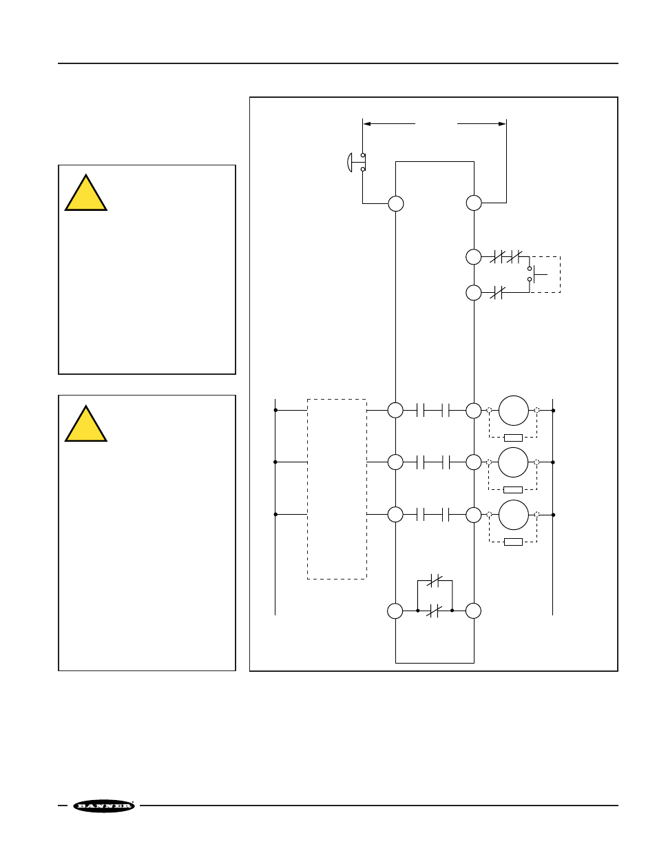
24V ac/dc
Emergency
Stop Switch
Reset
Switch
(jumper for auto reset -
see Warning on page 7)
MSC1 MSC3
MSC2
MSC Monitor
Contacts
L2
A2
MSC1
ES-FA-6G
MSC2
Machine
Master Stop
Control Elements
*Arc suppressors
(see WARNING)
K2D
Non-safety
Auxiliary
Monitor Contact
6A Max.
K1
A
6A max.
6A max.
6A max.
K2
A
K1
B
K2
B
K1
C
K2
C
*
MSC3
A1
13
14
23
24
33
34
41
42
Y2
Y1
L1
Machine
Control
Circuits
dc common
+V
K1D
Figure 2. Hookup of ES-FA-6G E-Stop Safety Module
WARNING . . .
If arc suppressors are
used, they MUST be
installed as shown
across the actuator coil of the
Master Stop Control Elements
(MSC1 to MSC4). NEVER install
suppressors directly across the
output contacts of the E-stop Safety
Module. It is possible for
suppressors to fail as a short circuit.
If installed directly across the output
contacts of the Safety Module, a
short-circuited suppressor will
create an unsafe condition which
could result in serious injury or
death.
!
WARNING . . .
NEVER wire an
intermediate device (for
example, a programmable
logic controller), other than a Safety
Relay, between E-stop Safety Module
outputs and the Master Stop Control
Element it switches. To do so
sacrifices the control reliability of the
control-to-machine interface, and
creates an unsafe condition which
could result in serious injury or death.
Whenever a Safety Relay is added as
an intermediate switching device, a
normally closed forced-guided monitor
contact of that relay must be added to
the series feedback loop between
Safety Module terminals Y1 and Y2.
(Reference ANSI B11.1 – 1988,
Appendix B4)
!