Msa series stands, Mounting sensor or mirror to pole – Banner MSA Series Stands User Manual
Page 3
P/N 43687 rev. C
3
MSA Series Stands
Banner Engineering Corp.
•
Minneapolis, MN U.S.A.
www.bannerengineering.com • Tel: 763.544.3164
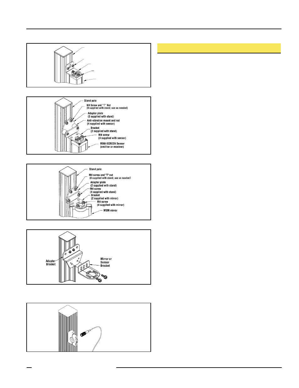
Figure 4. Sensor-to-stand mounting for MINI-SCREEN sensor
Figure 5. Mirror-to-stand mounting for MSM Series mirror
Stand Pole
Bracket
(2 supplied with sensor)
2x M3 Screw
(supplied with sensor)
M4 Screw and "T" Nut
(8 supplied with stand; use as needed)
MICRO-SCREEN
(emitter/receiver)
Figure 3. Sensor-to-stand mounting for MICRO-SCREEN sensor
Mounting Sensor or Mirror to Pole
1) Verify that all poles used for the light screen installation are
exactly parallel to each other before mounting sensors and/
or mirrors.
2) Refer to Figures 3, 4, 5, 6, and 7. Assemble the brackets and
hardware as shown in the appropriate figure.
3) Loosely mount the bracket assemblies (see step 2, above) to
the pole using the M4 screws and “T” nuts supplied with the
stand†.
Note that Figures 3, 4 and 5 show the bracket assembly
pointed “outward” (away from the sensor or mirror). One
or both of the bracket assemblies may be reversed to point
“inward,” if necessary. However, access to the mounting
screws becomes less convenient and mirror rotation is
limited when a bracket assembly is pointed inward.
4) Mount the sensor or mirror to its brackets using the screws
supplied with the sensor or mirror. Temporarily tighten those
screws. (NOTE: MICRO-SCREEN sensors from 40" to 48"
long also include one center bracket, and MICRO-SCREEN
sensors from 52" to 72" long include two center brackets.
M4 and “T” nuts are provided with the stands for these
situations. See the MICRO-SCREEN installation manual for
further details.)
5) Slide the sensor or mirror into position along the length of
the pole and tighten the M4 screws into their “T” nuts to lock
the sensor or mirror into position.
IMPORTANT: Step 5 requires accuracy. If no mirrors are
involved in the sensing path, then any feature of the emitter
can be matched in vertical position with the same feature on
the receiver. However, if one or more mirrors is used, the
center of each mirror must match the vertical position of
the center of the defined area of the sensors. The upper and
lower limits of the defined area are dimensioned in the light
screen instruction manual.
6) Loosen the bracket screws (tightened in Step 4) to allow the
sensor or mirror to rotate for alignment. See the light screen
instruction manual for alignment information.
Figure 6. Adapter bracket-to-stand mounting, shown ready for
mounting of EZ-SCREEN or MACHINE-GUARD sensor or
SSM-Series mirror
Figure 7. Swivel bracket-to-stand mounting for SFP12 or
SFP30 Point