Aligning sensors and corner mirrors, Range reduction using ssm-s series corner mirrors – Banner SSM Series Corner Mirrors User Manual
Page 3
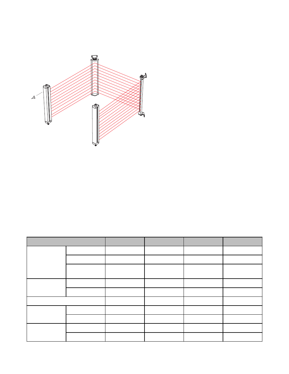
Aligning Sensors and Corner Mirrors
Component #2
(Mirror)
Component #3
(Mirror)
Component #4
(Receiver)
Component #1
(Emitter)
Figure 1. Corner Mirror Alignment
Mount the mirror(s) and the sensors so that they are all par-
allel. Use a level, if possible. Adjust the position of the sen-
sors and the mirror(s) so that the midpoints of the mirror(s)
and the sensors’ defined areas are even. (A line connecting
the midpoint of all components is illustrated by the dashed
line in the drawing.) The midpoint of the defined area of a MI-
CRO-SCREEN or EZ-SCREEN sensor is the midpoint of the
window. The upper and lower limits of the defined area of
MINISCREEN sensors are marked by arrows along the edge
of each sensor window, and are dimensioned in the appropri-
ate instruction manual. The midpoint of the defined area of
MACHINE-GUARD/PERIMETER-GUARD sensors corre-
sponds to the midpoint of the sensor length. For EZ-
SCREEN Grid sensors, the midpoint is between the top and
bottom dots on the housing, adjacent to the sensing window.
Adjust the corner mirror(s) so that the angle of incidence to
the mirrors equals the angle of reflection from the mirror.
Sight from behind one of the sensors directly towards the
mirror (or the first mirror in line). When alignment is correct,
you will see the straight and centered reflection of the lens of
the other sensor in the mirror.
Use the alignment indicator(s) of the safety light screen sys-
tem (and the appropriate instruction manual) for final align-
ment.
Range Reduction Using SSM-S Series Corner Mirrors
Use of corner mirrors reduces light screen range (the maximum separation between the emitter and receiver). The following table lists the
resultant range when using from one to three SSM-S Series corner mirrors in the sensing path.
Maximized excess gain is always important when installing a safety light screen. Use hard guarding whenever possible to reduce the
overall sensing range and the number of mirrors required. Also, keep sensor lenses and mirrors clean and properly aligned.
Table 1: Light Screen/Light Grid Maximum Range
Light Screen/Light Grid Sensors
0 Mirrors
1 Mirror
2 Mirrors
3 Mirrors
MICRO-SCREEN
Standard Series
9 m (30')
7.1 m (23')
5.5 m (18')
4.2 m (14')
V-Series – 24" to 48"
9 m (30')
7.1 m (23')
5.5 m (18')
4.2 m (14')
V-Series – 56", 64",
72"
6 m (20')
4.7 m (15.5')
3.7 m (12')
2.8 m (9')
MINI-SCREEN
Standard Series
9 m (30')
7.1 m (23')
5.5 m (18')
4.2 m (14')
XL-Series
18 m (60')
14.2 m (46.5')
11 m (36')
8.5 m (28')
MACHINE-GUARD/ PERIMETER-GUARD
14 m (45')
10.6 m (35')
8.2 m (27')
6.4 m (21')
EZ-SCREEN Grid/
Point
Short-Range
20 m (65')
15.3 m (50')
12 m (39')
9.2 m (30')
Long-Range
70 m (230')
54.3 m (178')
42.1 m (138')
32.6 m (107')
EZ-SCREEN
14 mm Resolution
6 m (20')
4.7 m (15.5')
3.7 m (12')
2.8 m (9')
30 mm Resolution
18 m (60')
14.2 m (46.5')
11 m (36')
8.5 m (28')
SSM-S Stainless Steel Corner Mirrors
P/N 67200 Rev. C
www.bannerengineering.com - tel: 763-544-3164
3