Sensor startup sensor startup, Step – Banner PresencePLUS BCR 1.3 Series User Manual
Page 7
P/N 118000 rev. D
7
Banner Engineering Corp.
•
Minneapolis, MN U.S.A.
www.bannerengineering.com • Tel: 763.544.3164
sensor
startup
sensor
startup
. Install the PresencePLUS software.
a. Insert the Installation CD.
b. Click Install PresencePLUS PC Software.
step
step
Launching Software
1. Start the PresencePLUS program by clicking
Start > Program Files > PresencePLUS.
. At start-up, PresencePLUS will try to communicate with the Sensor.
If communication with the Sensor is successful, the application will launch and
display the Setup or Run screen. If communication was not successful:
• Verify that the Ethernet cable is the correct type (see Cable Connections on
page 4).
• Verify that the TCP/IP settings are correct (see PC Configuration on
page 6).
3. If using an optional NTSC video monitor, verify that the monitor is displaying an
image. You may not see an image until the camera is given the first trigger.
. When the software launches, create an inspection, configure the discrete I/O,
and begin running inspections.
NOTE: Initially, all discrete I/O are configured as inputs. Go to the System window
to change the discrete I/O. For detailed configuration information, refer to
the User’s Manual (under the Help button in the GUI; see back cover for part
number).
step
step
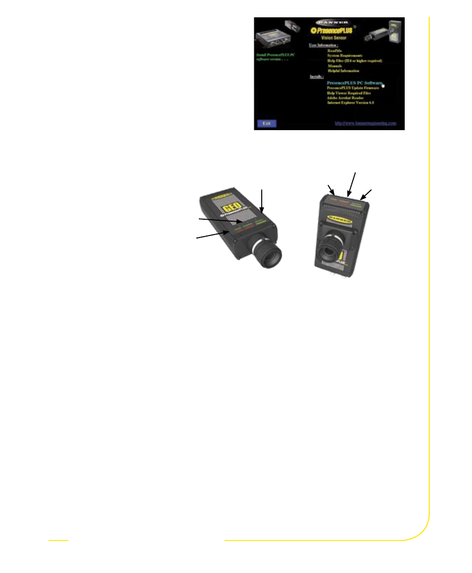
Starting the PresencePLUS P4
1. Power up the hardware and verify
that the Power/Error light turns
Green. This may take up to 20
seconds.
. Verify that the yellow LED on
the Ethernet port is ON.
If it is not ON, see
Cable Connections
on page 4.
Green = Ready
Yellow = Trigger
Green = Ready
Yellow = Trigger
Green = Power
Red = Error
Green = Power
Red = Error
Green = Pass
Red = Fail
In-Line Sensor
Right-Angle
Sensor
Green = Pass
Red = Fail