Components/ connections components/ connections, Step 1, Step – Banner PresencePLUS BCR 1.3 Series User Manual
Page 4
P/N 118000 rev. D
Banner Engineering Corp.
•
Minneapolis, MN U.S.A.
www.bannerengineering.com • Tel: 763.544.3164
components/
connections
components/
connections
a. Caution: If the light is powered by the Sensor, the
Sensor power source must be 24V dc.
b. Caution: This connection is for Banner lights only!
. If an NTSC monitor is used, connect it to the Sensor via a
BNC-to-BNC cable to the NTSC Video connector.
3. Connect the Ethernet cable from your PC to the Sensor at
the RJ-45 connector.
a. If connecting directly from the PC, use a crossover
cable (such as Banner Model No. STPX07).
b. If connecting the Sensor to a hub or router, use
straight cables (such as Banner Model No. STP07) to
the Sensor as well as to the PC.
. Push the connector end of the supplied 12-wire cable
onto the 12-pin connector on the Sensor.
step 1
step 1
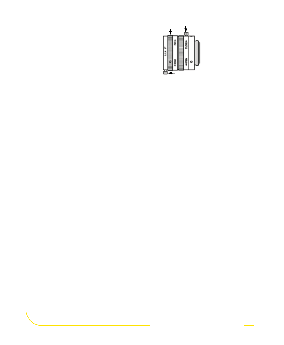
1. Install the lens (and filters, if used).
For EDGE, GEO, BCR, AREA, and OMNI any
lens may be used. For EDGE 1.3, GEO 1.3,
AREA 1.3, BCR 1.3, and OMNI 1.3 use only
Megapixel lenses. For non-Banner lenses,
follow the lens manufacturer’s unpacking
and installation instructions.
Cable Connections
1. If a light will be powered by the Sensor,
connect it to the
Light connector.
step
step
Focusing
Ring
Aperture Lock
Screw
Focus
Lock Ring
NOTE: If the lens has a focus
lock screw, loosen the
screw before focusing
the lens. Some lenses
also have an aperture
lock screw.