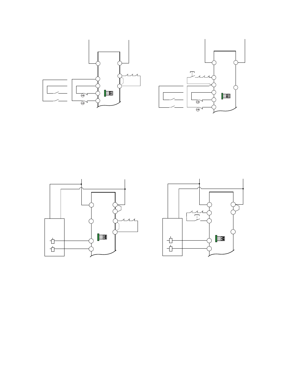
Figure 5, Figure 4, Manual reset – Banner Universal Input Safety Modules User Manual
Page 7: Auto reset
Reset
A2
(No
Connection)
A1
S34
S11
S33
MSC1 MSC2 MSC3
S22
S12
S21
0V
+24V ac/dc
UM-FA-..A
Manual Reset
Devices with
relay output
contacts
Devices with
positive-opening
contacts
DIP Switch
Configuration
See Interfacing MSCs
WARNING
A2
A1
S21
S11
S12
S22
0V
+24V ac/dc
UM-FA-..A
Auto Reset
MSC1
MSC3
MSC2
MSC
Monitor
Contacts
or
Jumper
S33
S34
Devices with
relay output
contacts
Devices with
positive-opening
contacts
DIP Switch
Configuration
1
2
ON
1
2
ON
Dual-Channel Hookup Configuration for Devices with Hard Contacts
Figure 4.
+
+
MSC1
MSC3
MSC2
A2
A1
S34
S33
S11
S12
S22
0V dc
0V
+24V dc
+24V dc
+24V dc
+24V dc
UM-FA-..A
Manual Reset
Reset
(No
Connection)
1
2
ON
DIP Switch
Configuration
S21
+
+
A2
A1
S11
S12
S22
0V dc
0V
+24V dc
+24V dc
UM-FA-..A
Auto Reset
MSC1
MSC3
MSC2
MSC
Monitor
Contacts
or
Jumper
S33
S34
+24V dc
+24V dc
1
2
ON
DIP Switch
Configuration
S21
Dual-Channel Hookup Configuration for Solid State Devices (+24V dc Supply Only)
Figure 5.
UM-FA-xA Universal Input Safety Modules
P/N 141249_web
Rev. E
www.bannerengineering.com - tel: 763-544-3164
7
- EZ-SCREEN Systems—Type 2 (71 pages)
- EZ-SCREEN Lens Shields (4 pages)
- EZ-SCREEN Lens Shields (2 pages)
- MMD-TA-12B Muting Modules (60 pages)
- Enclosures (4 pages)
- Enclosures (4 pages)
- Enclosures (2 pages)
- Enclosures (2 pages)
- Enclosures (2 pages)
- Compact Metal Style Safety Interlock Switches (8 pages)
- EZ-SCREEN™ Point (60 pages)
- EZ-SCREEN™ Grid (64 pages)
- Safe Speed Monitoring Modules (8 pages)
- Safe Speed Monitoring Modules (15 pages)
- EZ-SCREEN® LP Low-Profile Safety Light Screen (74 pages)
- EZ-SCREEN® LP Low-Profile Safety Light Screen (76 pages)
- EZA-MBK-21 (4 pages)
- SI-LS42 Locking Style Switches (12 pages)
- SI-LS42 Locking Style Switches (8 pages)
- SC22-3 Safety Controller (130 pages)
- SC22-3 Safety Controller (15 pages)
- EZAC-RM-1 Relay Module (2 pages)
- MSA Series Protective Mounting Stands (4 pages)
- EZ-SCREEN® AC Interface Box (16 pages)
- Mechanical E-Stop Buttons (5 pages)
- RP-QM90 Rope Pull Switch (8 pages)
- Hinge Style Safety Interlock Switches (8 pages)
- Hinge Style Safety Interlock Switches (7 pages)
- Hinge Style Safety Interlock Switches (14 pages)
- GM-FA-10J Safety Module (16 pages)
- GM-FA-10J Safety Module (13 pages)
- GM-FA-10J Safety Module (12 pages)
- SI-MAG Series Magnet Style Switches (22 pages)
- DUO-TOUCH SG Two-Hand Control Safety Modules (14 pages)
- DUO-TOUCH Two-Hand Control Modules (12 pages)
- DUO-TOUCH SG Two-Hand Control Safety Modules (1 page)
- DUO-TOUCH SG Two-Hand Control Safety Modules (20 pages)
- EZ-LIGHT™ for EZ-SCREEN® (4 pages)
- Compact Plastic Style Safety Interlock Switches (8 pages)
- Compact Plastic Style Safety Interlock Switches (10 pages)
- DUO-TOUCH Run Bar with STB Buttons (11 pages)
- DUO-TOUCH Run Bar with STB Buttons (17 pages)
- SSM Series Corner Mirrors (4 pages)
- SMBPPDE Mounting Bracket (1 page)