Msa-te series tubular enclosures, Assembly instructions – Banner Enclosures User Manual
Page 3
P/N 109307 rev. B
3
MSA-TE Series Tubular Enclosures
Banner Engineering Corp.
•
Minneapolis, MN U.S.A.
www.bannerengineering.com • Tel: 763.544.3164
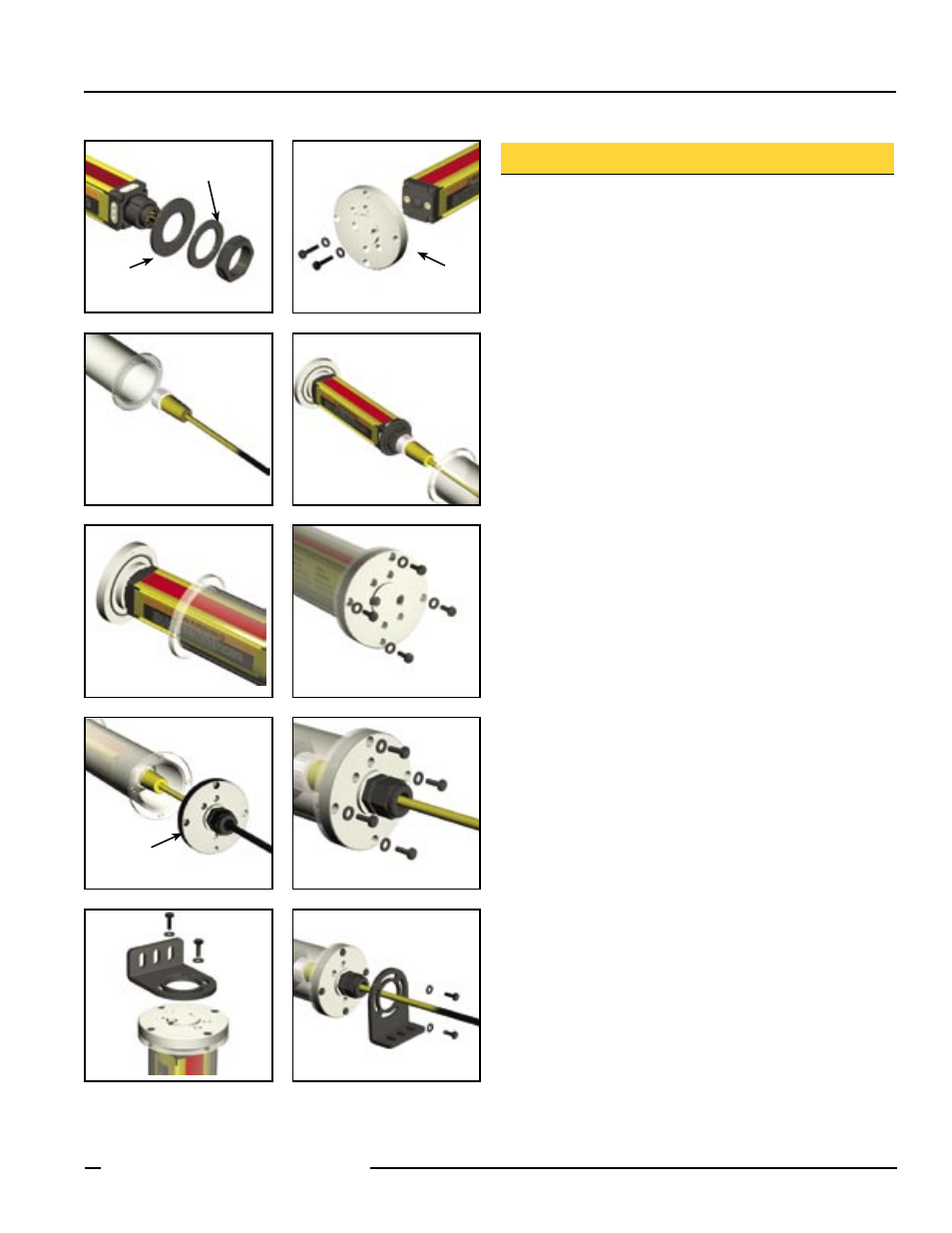
Assembly Instructions
A. Place spacer disk on the QD end of the MINI-SCREEN sensor,
using the plastic mounting nut and lockwasher (supplied with
MINI-SCREEN).
B. Screw the top cap onto the non-QD end of the MINI-SCREEN
using the two M4 screws and lockwashers (make sure o-ring
is in place on top cap). Torque: 6 in-lbs max.
C. Being careful not to scratch the tubular housing, slide the
terminated end of the cordset into the labeled end of the clear
tube and push it through, so it comes out the other end.
D. Connect the cordset to the MINI-SCREEN.
E. Slide the MINI-SCREEN into the clear tube until the top cap
mates with the tube flange. Make sure the o-ring seals against
the flat surface of the flange.
F. Screw the top cap to the tube flange using four 6-32 screws
and lockwashers. Torque: 15 in-lbs max.
G. Slide the bottom end cap over the unterminated end of the
cordset, making sure the o-ring is in place on the bottom cap.
H. Screw the bottom cap to the tube flange, using four 6-32
screws and lockwashers. Make sure the o-ring seals against
the flat surface of the flange. Torque: 15 in-lbs max. Tighten
the strain relief nut over the cordset cable.
I. Place the mounting bracket on the top cap and secure with
two 10-32 screws and lockwashers. Torque: 50 in-lbs max.
J. Place the mounting bracket over the cordset cable and to
the bottom end cap; secure with two 10-32 screws and
lockwashers. Torque: 50 in-lbs max.
A
B
C
D
E
F
Figure 3. MSA-TE Series Tubular Enclosure assembly steps
G
H
I
J
Lockwasher
O-ring
(backside)
O-ring
(backside)