A.2 serial data format and header string, Appendix a: data transmission – Banner A-GAGE High-Resolution MINI-ARRAY Series User Manual
Page 34
P/N 64118 rev. B
Appendix A: Data Transmission
34
Banner Engineering Corp.
•
Minneapolis, U.S.A.
www.bannerengineering.com • Tel: 763.544.3164
Appendix A: Data Transmission
A.1 Host Mode Command String
As discussed in section 5.3.2 of this manual, the control module has three control
mode options: continuous, gate, and host. Host mode requires a serial transmission
string from a separate device, typically a PC or process controller. The serial
transmission medium can be either RS-485 or RS-232.
When Host control mode is selected, the host process controller initiates scans using a
command string. The command string is a three-byte message, consisting of:
• Control byte with decimal value 248,
• Controller ID (the identification of a specific control module on the string, indicated
by one of 15 ASCII letters A through O, and specified in the PSF), and
• Scan initiation byte (ASCII letter S).
The command string is further defined as follows:
/*the below C code will define an array called msg that will contain the Host Scan Command */
unsigned char msg[3]; /*declare three byte unsigned character array using C language */
msg[0]=248; /*control byte */
msg[1]=65; /*assume the controller ID is the letter A */
msg[2]=83; /*assume initiation byte which is the ASCII letter S */
The host transmits this three-byte message at the defined baud rate. The format is one
start bit, one stop bit, even parity, and eight data bits. When the control module
receives this message, it initiates a scan (assuming Host mode is selected) and then
updates its outputs as required. The control module then waits for the next Host
Command message before initiating another scan.
A.2 Serial Data Format and Header String
The programmed measurement mode or modes determine the type of information that
is serially transmitted. For example if Meas1 is set for FBB and Meas2 is set for LBB,
then the data transmitted to the host contains the values of the first and last beam
blocked. The All measurement mode provides the status of all beams to the host.
In addition to measurement mode information, the data transmission also contains a
two-byte start string and a termination byte. The start string consists of a first byte that
does not change, followed by the controller ID. The first byte value is a hex 1C or 28
decimal. At the end of the string, the control module will place a termination byte. The
termination bye is the ASCII character for a linefeed (hex value 0A). These three bytes
collectively are called the Serial Header string.
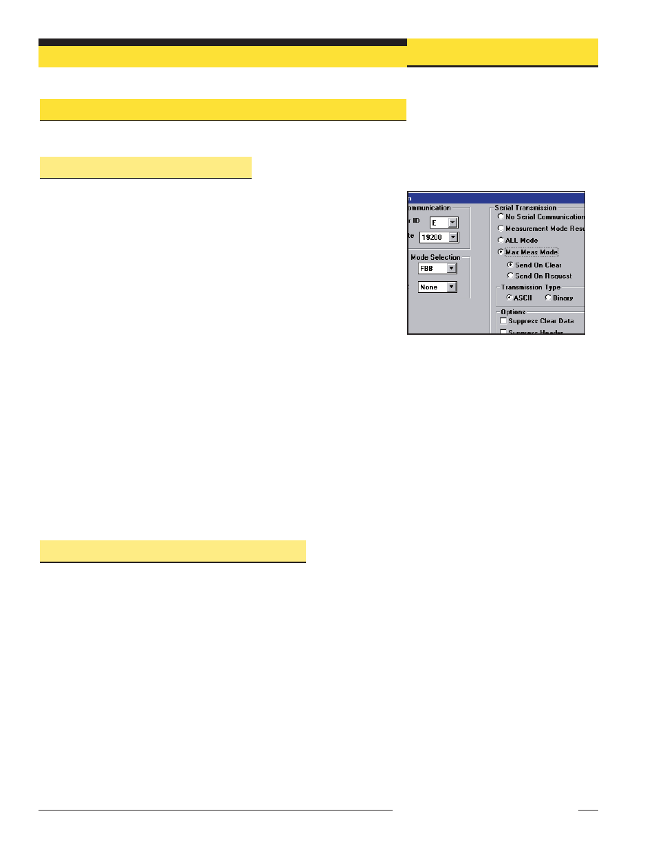
Figure A-1. Serial Transmission options
(PSF Configuration screen)