1 emitter and receiver hookups, 2 inputs, 3 outputs – Banner A-GAGE High-Resolution MINI-ARRAY Series User Manual
Page 15: Installation and mechanical alignment
15
Banner Engineering Corp.
•
Minneapolis, U.S.A.
www.bannerengineering.com • Tel: 763.544.3164
P/N 64118 rev. B
2 - TX
3 - RX
5 - COM
RS-232
5
3 2
Installation and Mechanical Alignment
Serial Communication
RS-232: All A-GAGE High-Resolution MINI-ARRAY Systems may communicate with a
host computer or controller via RS-232 or RS-485 serial protocol. See
Section 5.3.1 for selectable communications parameters. Prepare an RS-232
cable using a male DB-9 connector with connections as shown in Figure 3-8.
NOTE: DO NOT use a “null modem” RS-232 cable
RS-485: RS-485 serial port is located at terminals #18 (TX) and #19 (TX).
DB-9 Pin #
Function
2
Transmit (TX)
3
Receive (RX)
5
Ground (GND)
3.3.1 Emitter and Receiver Hookups
Emitters and receivers connect together in parallel to terminals #4 through #8 of the
control module (identical for all control module models). See Figures 3-3, 3-4, 3-5, and
3-6 for wire color information.
3.3.2 Inputs
System Power: Connect a source of 16 to 30V dc, rated at 1 amp or greater, to control
module terminals #1 (+) and #2 (-). Connect a good earth ground to terminal #3 to
provide electrical and RF noise immunity to the System.
NOTE: Remove power before making other connections to the controller.
Gate Signal: A source of 10 to 30V dc switched to terminals #12(+) and #13(-)
provides a gating input (if required). The gating voltage typically is switched by the
open-collector output transistor of a dc sensing device. The gate signal controls
scanning when one of four Gate options is selected in the Control Mode Selection
menu of the PSF configuration routine (see Section 5.3.2).
Align: A source of 10 to 30V dc switched to terminals #14(+) and #15(-) provides a
remote means of running the automatic alignment and blanking routines. The switch
sequence is identical to the procedure described in Section 5.2.1 for the Alignment
switch on the front of the control module.
Control Module
Analog Outputs
(Terminals #10 and 16)
Discrete Outputs*
(Terminals #9 and 20)
MAHCVN-1
Figure 3-3
0 to 10V Sourcing
15 mA max.
NPN open-collector
30V dc max.
150 mA max.
MAHCVP-1
Figure 3-4
0 to 10V Sourcing
15 mA max.
PNP open-collector
30V dc max.
MAHCIN-1
Figure 3-5
4 to 20 mA
Sinking
16 to 30V dc
NPN open-collector
30V dc max.
150 mA max.
MAHCIP-1
Figure 3-6
4 to 20 mA
Sinking
16 to 30V dc
PNP open-collector
30V dc max.
150 mA max.
*NOTE: Discrete Output #2 is labeled “Alarm” on the control module.
Figure 3-8. DB-9 connections between the
control module and the PC
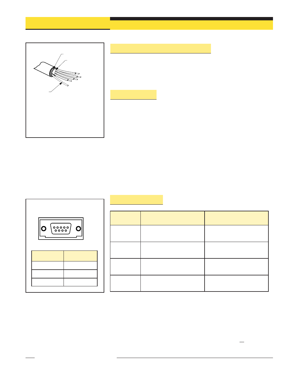
Trim braided shield flush
with cable
Trim foil shield flush
with cable
Uninsulated
drain wire
Figure 3-7. Emitter and receiver cable
preparation
Banner Engineering Corp.
•
Minneapolis, U.S.A.
www.bannerengineering.com • Tel: 763.544.3164
NOTE: The “drain wire” is the uninsulated
stranded wire which runs between the
braided shield and the foil shield. The foil
shield and the braided shield should be
removed at the point where the wires exit
the cable.
3.3.3 Outputs