1 diagnostics indicators, Diagnostics, System diagnostics – Banner A-GAGE High-Resolution MINI-ARRAY Series User Manual
Page 32: A / b, Error no. error type/action, System is ok, Align / blank • status, Output short • check output load & wiring, Serial comm • check serial cable, Cpu error • replace control module
P/N 64118 rev. B
System Diagnostics
32
Banner Engineering Corp.
•
Minneapolis, U.S.A.
www.bannerengineering.com • Tel: 763.544.3164
6. System Diagnostics
System diagnostics may be performed using the status and diagnostics indicators on the
control module and sensors, or by using the Diagnostics software routine, or a
combination of the two.
6.1 Diagnostics Indicators
NOTE: Status indicators appear to “freeze” if the controller has been configured for Gate
or Host mode (Section 5.3.2), and no signal is present to cause a scan update.
DIAGNOSTICS
Error No.
Error Type/Action
–
System is OK
A / b
Align / blank
• Status
1
Output Short
• Check output load & wiring
2
E / R Mismatch
• System must use same length
emitter and receiver
3
Receiver Error
• Check receiver cable
• Replace receiver
4
Emitter Error
• Check emitter cable
• Replace emitter
5
Serial Comm
• Check serial cable
6
EEPROM
• Reconfigure PSF
• Replace control module
• Reconfigure blanking
7
CPU Error
• Replace control module
8
Null / Span
• Status
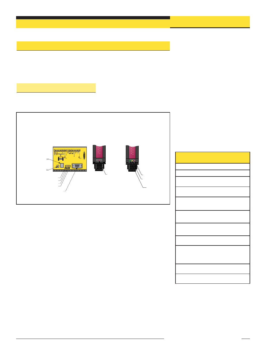
Figure 6-2. Key to System Diagnostics
Indicator codes
Red
Operational
LED
Green Alignment LED
Red Blocked LED
Yellow Marginal
Alignment LED
High-Resolution
Emitter
High-Resolution
Receiver
DIN-Rail-Mountable
Control Module
HIGH RESOLUTION MINI-ARRAY CONTROLLER
ALIGNMENT
SWITCH
POWER
POWER
DIAGNOSTICS
INDICATOR
2 - TX
3 - RX
5 - COM
RS-232
MAHCVP-1
OUTPU
T
ALAR
M
GA
TE
ALIGN
1
+
–
+
–
16-30V dc
1A MAX
10-30VDC
GATE
D OUT 1
150mA MAX
0-10VOLTS
25mA (MAX)
V OUT 1
EMTR
RCVR
2
3
4
5
6
7
8
9 10 11 12 13 14 15 16 17 18 19 20
F1
+12V COM DRN T/R T/R
BR BU
BK WH
TX TX
+
–
10-30VDC
ALIGN
0-10VOLTS
25mA (MAX)
V OUT 2
+V
ALARM
150mA MAX
+V
Diagnostics Indicator
Alignment Button
Red Discrete Output #1 LED
Red Alarm (Discrete Output #2) LED
Red Gate LED
Green Align LED
RS-232 Port
Figure 6-1. A-GAGE High-Resolution MINI-ARRAY System diagnostics and status indicators
Bright, easy-to-see LED indicators on both sensors and on the front panel of the
control module provide an ongoing display of the system’s operating status.
Control Module:
OUTPUT: (red) displays the status of Discrete Output #1.
ALARM: (red) displays the status of Discrete Output #2. This output may be assigned
to an analysis mode, or it may be used as a System Diagnostics alarm or as a Trigger
alarm to gate another A-GAGE High-Resolution MINI-ARRAY System.
GATE: (red) displays the status of the Gate input.
ALIGN: (green) indicates proper emitter/receiver alignment and a clear, unblocked light
screen. This indicator is ON when either the green or both the green and yellow LEDs
of the receiver are ON.