1 communications setup, 1 ping routine, Control module configuration – Banner A-GAGE High-Resolution MINI-ARRAY Series User Manual
Page 17
17
Banner Engineering Corp.
•
Minneapolis, U.S.A.
www.bannerengineering.com • Tel: 763.544.3164
P/N 64118 rev. B
Control Module Configuration
Banner Engineering Corp.
•
Minneapolis, U.S.A.
www.bannerengineering.com • Tel: 763.544.3164
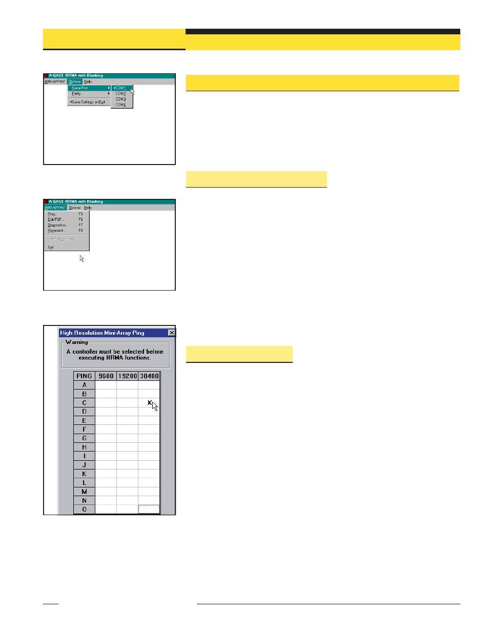
Figure 5-1. Options menu, serial port
selection
Figure 5-2. MINI-ARRAY menu
Figure 5-3. Screen showing the result of a
completed Ping routine
5. Control Module Configuration
The A-GAGE High-Resolution MINI-ARRAY control module is easily configured using a
Windows® menu-style routine; the configuration routine requires the Banner-supplied
HRMA software and a PC-compatible computer (running Windows® XP, Vista, or 7)
A serial data connection is made between the computer and the DB9 connector on the
control module.
5.1 Communications Setup
After installing the software, attach the serial communication cable between the control
module and the PC. (NOTE: If an RS-232 interface is used, only one control module is
allowed on the line at any one time.) The minimum connections to the control module’s
DB-9 connector are shown in Figure 3-8.
Launch the High-Resolution MINI-ARRAY program and configure the serial
communications port of the PC. Select the Options menu from the High-Resolution
MINI-ARRAY main menu (see Figure 5-1). The program supports serial communication
via the
COM1-COM20.port of the computer. Highlight the desired
serial port to select it (a “bullet” will appear next to the selected option), then select
Save Settings on Exit to store the serial port selection, if it is not already ON (a
“bullet” will appear next to the option, if it is ON).
Parity is selected here also: Even, Odd or None.
5.1.1 Ping Routine
The Ping routine must be performed during System configuration, and before any
Diagnostic, Alignment, or Edit routine. The routine polls all control modules on the
communications line (one, in the case of the standard RS-232 line, or up to 15
modules, on an RS-485 circuit). It then is used to select an individual control module
for configuration or alignment.
If needed, apply power to the System control module and allow the System to
complete its power-up routine. Press F5 or access the MINI-ARRAY menu and select
Ping to perform the Ping routine. All connected control modules will then identify
themselves with an ID value and baud rate; the routine takes approximately 15 to 20
seconds. After the Ping is performed, all valid control module ID values will appear in a
chart on the screen, under their appropriate baud rates (see Figure 5-3). Control
modules are identified in the chart as ‘X.’ Point to a valid ID with the mouse pointer
and click to select a control module. System Diagnostics, Alignment, or Edit routines
may now be performed for the selected control module.