Control module configuration – Banner A-GAGE High-Resolution MINI-ARRAY Series User Manual
Page 28
P/N 64118 rev. B
Control Module Configuration
28
Banner Engineering Corp.
•
Minneapolis, U.S.A.
www.bannerengineering.com • Tel: 763.544.3164
5.3.7 Discrete Output Configuration (Analysis Mode Assignment)
Discrete outputs #1 and #2 (“Alarm”) may each be individually assigned to one of the
Scan Analysis Modes programmed in section 5.3.4 (see Figures 5-16 and 5-22).
Next to each discrete output assignment menu are Low and High
Set Point boxes. The number in each box identifies a beam in the
array (beam #1 being closest to the cabled end of the emitter and
the receiver). The Low and High Set Points may be changed by
clicking on a box and entering a new number.
When the selected Scan Analysis Mode involves first or last beam
blocked or made (unblocked), the assigned output will energize
when the beam identified during a scan falls within the range of
the set points. When the Scan Analysis Mode involves total beams
blocked or made, that assigned output will energize when the
value of total beams counted during a scan falls within the range
of the set points.
Note that the pull-down menus used for assignment of the Scan
Analysis Modes to the discrete outputs include two “Inverted” selections. When either
MEAS1 Inverted or MEAS2 Inverted is selected, that discrete output will de-energize
(turn OFF) whenever a scan analysis value falls within the range of the set points.
Hysteresis values for each end of the set point range may also be set (Figure 5-22).
Hysteresis determines the amount of change that must occur at each set point (High
and Low) to cause the associated output to change state. Hysteresis prevents
unstable output conditions when the scan analysis value exactly matches one of the
set points. The default hysteresis setting is one beam less than the Low Set Point and
one beam more than the High Set Point.
Scan # Provides another way, in addition to hysteresis settings, to smooth output
response. Outputs are updated only after the selected number of identical (within the
hysteresis limits) scans. The menu allows selection of from 1 to 9 scans. For discrete
outputs, the scan analysis value must stay either inside or outside the hysteresis
limits for all of the selected number of consecutive scans, in order for the output to
respond. See Figure 5-23.
Alarm and Trigger
Discrete output #2 (only) has two additional options: Alarm and Trigger.
Alarm: Output #2 energizes whenever the System detects a sensor error (such as a
disconnected cable) or whenever the excess gain of one or more beams becomes
marginal.
Trigger: can be used to gate a second control module when Continuous Scan Method
is also used. When the control module is in straight scanning mode, Trigger Channel
Number defines the beam number during a scan at which the trigger output will occur
(Figure 5-23). The Trigger output is a 100 microsecond (0.0001 sec.) pulse. If the
control module is set for single or double edge scan, the Trigger pulse will come at
the end of the scan (Trigger Channel Number will be ignored).
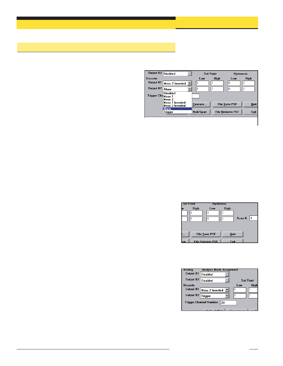
Figure 5-23. Scan # (PSF Configuration
Screen)
Figure 5-24. Trigger Channel
Figure 5-22. Assigning an Analysis Mode to each Discrete output
(PSF Configuration screen). Alarm and Trigger
output options are available only for Discrete
Output #2.