6 zero value, Control module configuration – Banner A-GAGE High-Resolution MINI-ARRAY Series User Manual
Page 27
27
Banner Engineering Corp.
•
Minneapolis, U.S.A.
www.bannerengineering.com • Tel: 763.544.3164
P/N 64118 rev. B
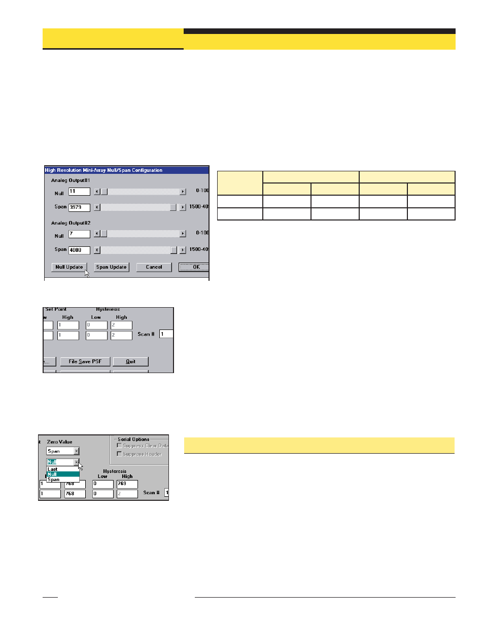
The Null and Span ranges may be adjusted as follows:
To read the new values on the meter, click on Null or Span Update. Click
on the OK button to save the new settings and return the program to the
PSF Configuration screen. Clicking on the Cancel button returns the
program to the previously saved null and span settings.
NOTE: Null and Span are factory set to specified values and usually require
no changes.
Scan # Provides a way to smooth output response and avoid unstable analog output
conditions. The menu allows selection of from 1 to 9 scans (see Figure 5-20). For
analog outputs, if scan # is set at more than 1, the scan analysis value is averaged for
all of the selected number of consecutive scans, preventing dips and spikes in the
outputs.
For total beam values (TBB and TBM analysis modes), programming of blanked
beams (section 5.2.3) will affect the proportional analog outputs. Blanked beams are
ignored both in the number of blocked or made beams and the total number of
beams. For example, if a 64-beam array has 20 blanked beams and 22 of the
remaining 44 beams are blocked, the output values will be at mid-range.
5.3.6 Zero Value
Zero value is used to specify the analog output when the measurement mode value is
zero. The user can select an analog output of LAST, NULL, or SPAN.
LAST: Output holds the last non-zero value before the light screen became clear.
NULL: Provides the minimum value
SPAN: Provides the maximum value.
The Null/Span Configuration screen (Figure 5-19), may be used to adjust the zero and
full scale reading for either analog output. To display the Null/Span Configuration screen,
click on the Null/Span button at the bottom of the PSF Configuration screen (Figure 5-9).
Each output is independent and must be adjusted separately. Adjust the Null and Span
values either by moving the slide bars, or by entering a new value on the keyboard.
To Measure:
Analog Voltage Output: Connect the voltmeter between terminals 10 or 16 (+) and 17 (–).
Analog Current Output: Connect the ammeter between terminals 10 or 16 (–) and 1 (+).
Analog
Output Type
Null
Span
Minimum
Maximum
Minimum
Maximum
Voltage
10 mV
2.3 V
4.8 V
10.1 V
Current
3.9 mA
7.8 mA
11.9 mA
20.2 mA
Figure 5-19. Null/Span Configuration screen
Figure 5-20. Scan # (PSF Configuration
screen)
Figure 5-21. Zero Value (PSF Configuration
screen)
Control Module Configuration
Banner Engineering Corp.
•
Minneapolis, U.S.A.
www.bannerengineering.com • Tel: 763.544.3164
NOTE: When in the Null/Span screen, the
controller will have a diagnostic
code of 8.