2 software alignment routine, Control module configuration – Banner A-GAGE High-Resolution MINI-ARRAY Series User Manual
Page 19
19
Banner Engineering Corp.
•
Minneapolis, U.S.A.
www.bannerengineering.com • Tel: 763.544.3164
P/N 64118 rev. B
5.2.2 Software Alignment Routine
The green LED indicator on the receiver and
also on the control module continuously
displays Alignment status. When all unblanked
beams are clear, the green Alignment
indicators will be ON. To better understand
blocked, clear and blanked beams, launch the
Alignment routine (press F8 or select
Alignment under the MINI-ARRAY menu). The
screen will show the state of all of the beam
channels, grouped into sets of 16.
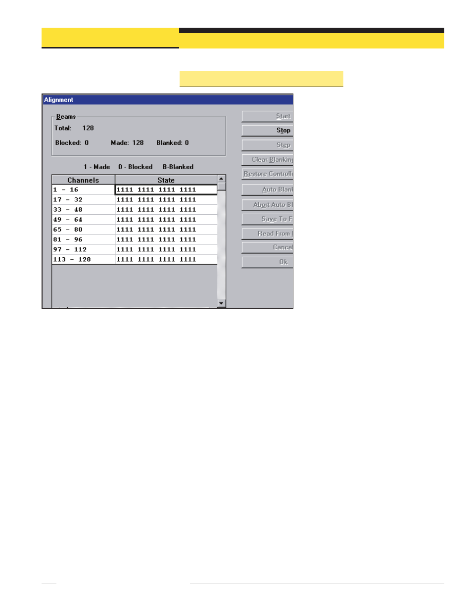
Key information provided on the Alignment
screen is the sensor size, plus the number of
beams blocked, made, and blanked. The
sensor size is given the title of “total”; this
refers to the total number of beam channels in
the array. The number of beams blocked is a
running total of blocked beams, excluding any
blanked beams. The “made” value is a count
of unblocked beams. The “blanked value” is a
count of the number of beam channels that are
blanked (channels that are ignored for
measurement mode applications; see section
5.2.3).
The Alignment screen provides the following functions: Start, Stop, Step, Clear
Blanking Fields, Restore Control module Settings, Auto Blanking, Abort Auto Blanking,
Save to File, Read From File, Cancel, OK, and Edit. To access any of these sub-routines,
first press Stop, then the selected option.
Start command causes the control module to continuously scan and report “All
Channel Data.” This data is used to update the state of each beam channel.
Stop command causes the control module to stop scanning.
Step command produces one scan and then stops until another command is issued.
Clear Blanking Fields command is a quick way to remove blanking specifications.
Restore Control Module Settings will recall the blanking specifications in effect prior
to Alignment/Blanking being entered.
Auto Blanking command is used to scan and determine which beams are blocked;
blocked beams automatically become blanked beams. The Auto Blanking values can
then be Accepted or Aborted.
Edit is used to control the blanking specifications of any channel manually. This is
useful for adding any number of blanked beam channels above and/or below a blanked
object to allow for vibration or other movement of the object to be ignored.
Blanking specifications can be saved and read from a computer file using the Save To
File and Read From File commands.
Figure 5-5. Alignment screen
Control Module Configuration
Banner Engineering Corp.
•
Minneapolis, U.S.A.
www.bannerengineering.com • Tel: 763.544.3164