3 control inputs and outputs – Metrohm 709 IC Pump User Manual
Page 55
5.2 Control interface
709 IC Pump
47
5.2.3
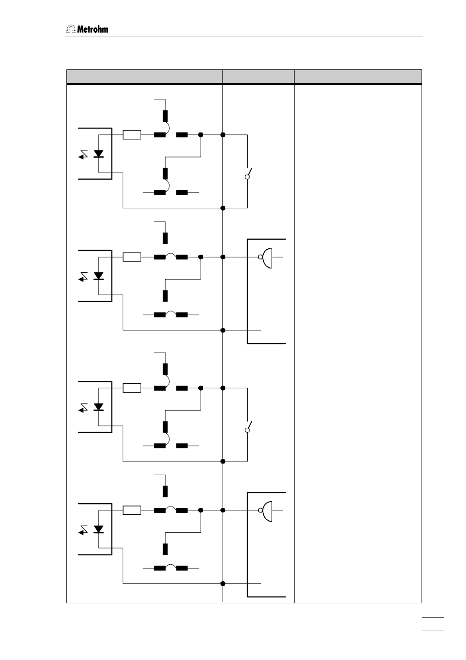
Control inputs and outputs
709 IC Pump
external
Function
Inputs
1k
+5V
P27.3
P27.2
P27.1
P28.3
P28.2
P28.1
1
2
1k
+5V
P27.3
P27.2
P27.1
P28.3
P28.2
P28.1
1
2
0V
0V
TTL
Reduced flow rate (Reduced Flow)
with contact
(default settings)
Contact open:
Flow rate 100%
Contact closed:
Flow rate 10%
With reduced flow, the "FLOW" LED 10
flashes.
Reduced flow rate (Reduced Flow)
with TTL logic signal
(Position of jumpers P27 and P28
must be changed, see
section 5.2.2)
Signal Low (L):
Flow rate 100%
Signal High (H):
Flow rate 10%
With reduced flow, the "FLOW" LED 10
flashes.
1k
+5V
P29.3
P29.2
P29.1
P30.3
P30.2
P30.1
7
8
1k
+5V
P29.3
P29.2
P29.1
P30.3
P30.2
P30.1
7
8
0V
0V
TTL
Stop pump with contact
(default setting)
Contact closed:
Pump is
stopped
Following a stop, the pump must be
restarted manually with the
key
.
Stop pump with TTL logic signal
(Position of jumpers P29 and P30
must be changed, see
section 5.2.2)
Signal High (H):
Pump is
stopped
Following a stop, the pump must be
restarted manually with the
key
.