2 control interface, 1 functions, 2 settings for the control interface – Metrohm 709 IC Pump User Manual
Page 54
5 Interfaces
709 IC Pump
46
5.2 Control
interface
5.2.1 Functions
The 709 IC Pump has the following control inputs and outputs, which
are accessible via the control interface:
Inputs
Reduce flow rate (possible via contact or TTL signal)
Stop pump (possible via contact or TTL signal)
Outputs
Signal when pump has been stopped or
Signal when pump is running
You will find detailed information on these functions in section 5.2.3,
possible changeover of the jumpers is described in section 5.2.2.
5.2.2
Settings for the control interface
If you wish to change the default settings for the control inputs and out-
puts (see section 5.2.3), proceed as follows:
The electronic circuitry of the 709 IC Pump is sensitive to electrostatic
charges. You should thus take the appropriate measures (earthing,
e.g. by touching metal) before opening the instrument.
1 Disconnect cables
Disconnect mains cable from mains connection plug 31 of the
709 IC Pump, also unplug all other cables connected to the rear
of the instrument.
2 Remove housing cover
Unscrew the two fastening screws 25 at the bottom of the
instrument and the two fastening screws 26 at the rear of the
instrument, remove housing cover 27.
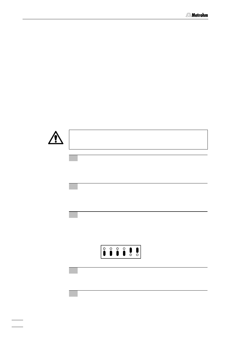
3 Change settings
Change over blue jumpers at positions P12, P27, P28, P29 and
P30 of the main board (on left side of instrument when viewed
from back) using tweezers or flat-nosed pliers to match the
settings you wish (settings, see section 5.2.3):
P13 P12
P27 P28 P29 P30
1
2
3
4 Replace housing cover
Replace housing cover 27 and fasten with fastening screws 25
and 26.
5 Plug in cables
Connect mains cable to mains connection plug 31 and also plug
in all other cables.
Default settings