Chart a – Brandmotion 9002-7605 User Manual
Page 2
2010-Current Ford Transit Connect Aftermarket CMOS Camera with Optional Parking
Gridlines Installation Instructions (Kit # 9002-7605)
7605 Ford Transit Connect Instructions 10-11-12.doc
Page 2 of 3
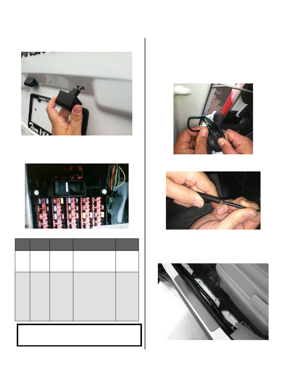
Step 5: Insert camera mount/license plate lamp
bezel assembly into access hole.
Step 6: Remove driver’s side kick panel and locate
vehicle Ignition and Ground signals. Use a multi-
meter or computer-safe test light to check Ignition and
Ground wires adjacent to the fuse block (Chart A).
Chart A
Wire
Color Polarity
Function
Description
Location
Red
12v +
Ignition
controlled
power
This lead will display
12 volt + when the
key is in the RUN
position
Found on
main
Ignition
harness.
Black
(-)
Ground
Chassis ground
A ground
bolt is
commonly
found in
the front
kick panel
area with
other
wires
attached.
Step 7: Splice the red and black Power Harness
leads into corresponding vehicle wires
(Recommended: Soldering or T-taps as optional
connection method). Also recommended is an eyelet for
the ground connection.
Step 8: Route Camera Harness. Route camera
harness through driver’s side rear door grommet.
Step 9: Connect Camera Harness to supplied
Chassis Harness.
Step 10: Route Chassis Harness. Run Chassis
Harness over the driver’s side wheel housing and
underneath the driver’s door sill to the driver’s side kick
panel. Use a plastic trim removal tool to avoid damage
to trim pieces.
CAUTION: Once correct wires have been identified,
turn Ignition key OFF and DO NOT TURN key back ON
until the install has been completed (Step 15).