Installation instructions – Brandmotion 9002-7607 User Manual
Page 2
INSTALLATION INSTRUCTIONS
7607 Chevrolet Express-GMC Savana Instructions 2-20-13.doc Page 2 of 2
Step 5: Connect Camera Harness jumper connector to
supplied Jumper Harness.
Step 6: Connect red wire of Jumper Harness to light
blue wire of CHMSL brake lamp (12+ brake lamp
power) and black wire to chassis ground (solder
recommended or T-Taps).
Wire
Color Polarity
Function
Description
Location
Red
12v +
CHMSL
illumination
Displays 12 volts +
with brakes applied
CHMSL
light blue
wire
Black
(–)
Ground
Brake light ground
CHMSL
black wire
Step 7: Attach supplied Camera using existing screws.
CAUTION: Do not over tighten.
Step 8: Connect Camera Harness video connector to
supplied Chassis Harness.
Step 9: Route Chassis Harness forward along the
drivers side wire channel at the base of the roof and
toward your video display / Navigation display.
Step 10: Connect Chassis Harness to supplied Video
Harness and route beneath headliner and down drivers
side A-pillar. (Note: connection is same as shown in Step 8.)
Step 11: (If necessary) Connect supplied Female to Male
RCA Adaptor to yellow RCA Video Harness plug.
Step 12: Connect yellow RCA plug of Video Harness to
“Camera IN” on the video / Navigation display. (NOTE:
The white RCA plug is not used in this application.)
Step 13: Connect Camera Harness power connector to
the supplied Power Harness.
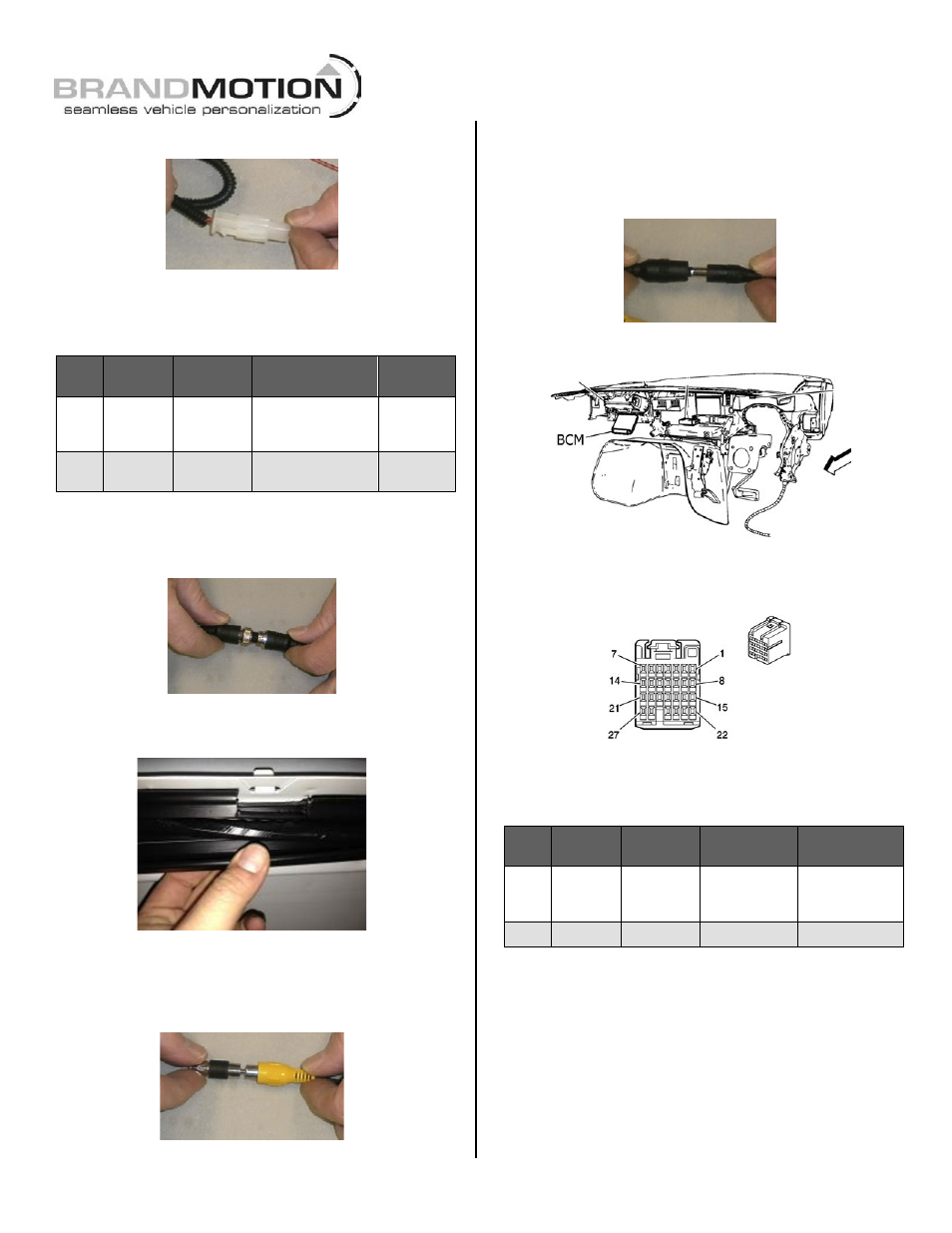
Step 14: Locate the Body Control Module (BCM) under
the passenger side of the dash.
Step 15: Splice the red wire from the Power Harness to
pink 12v+ Ignition power wire in cavity 2 of Body
Control Module (BCM) connector X1.
Step 16: Add a Ground Eyelet (recommended) to the
black wire from the Power Harness and use a screw or
nut to attach it to chassis ground (solder recommended or
T-Taps).
Wire
Color Polarity
Function
Description
Location
Red
12v +
Camera
power
Displays 12
volts + with
Ignition ON
BCM Connector
cavity 2 - Pink
wire
Black
(–)
Ground
Ground
Chassis
Step 17: Test the system. Inspect that all connections are
proper and secure. Clear all loose items removed from area
around the vehicle. Turn ignition key ON and shift into Reverse
to test system. The video image from the Camera should
appear in your display / Navigation display.
Step 18: Secure Chassis, Video, and Power Harnesses
to existing vehicle wiring and reassemble vehicle by
following your disassembly steps in reverse. Avoid
binding or otherwise damaging the harnesses.
(Recommended: Wire Ties or Electrical Tape.