Mirror harness pinout, Wiring the mirror – Brandmotion 9002-9516 User Manual
Page 2
9516 Instructions 9-27-12
Tel
734-619-1250
2 of 3
Toll Free
877-276-6456
Fax
480-247-5999
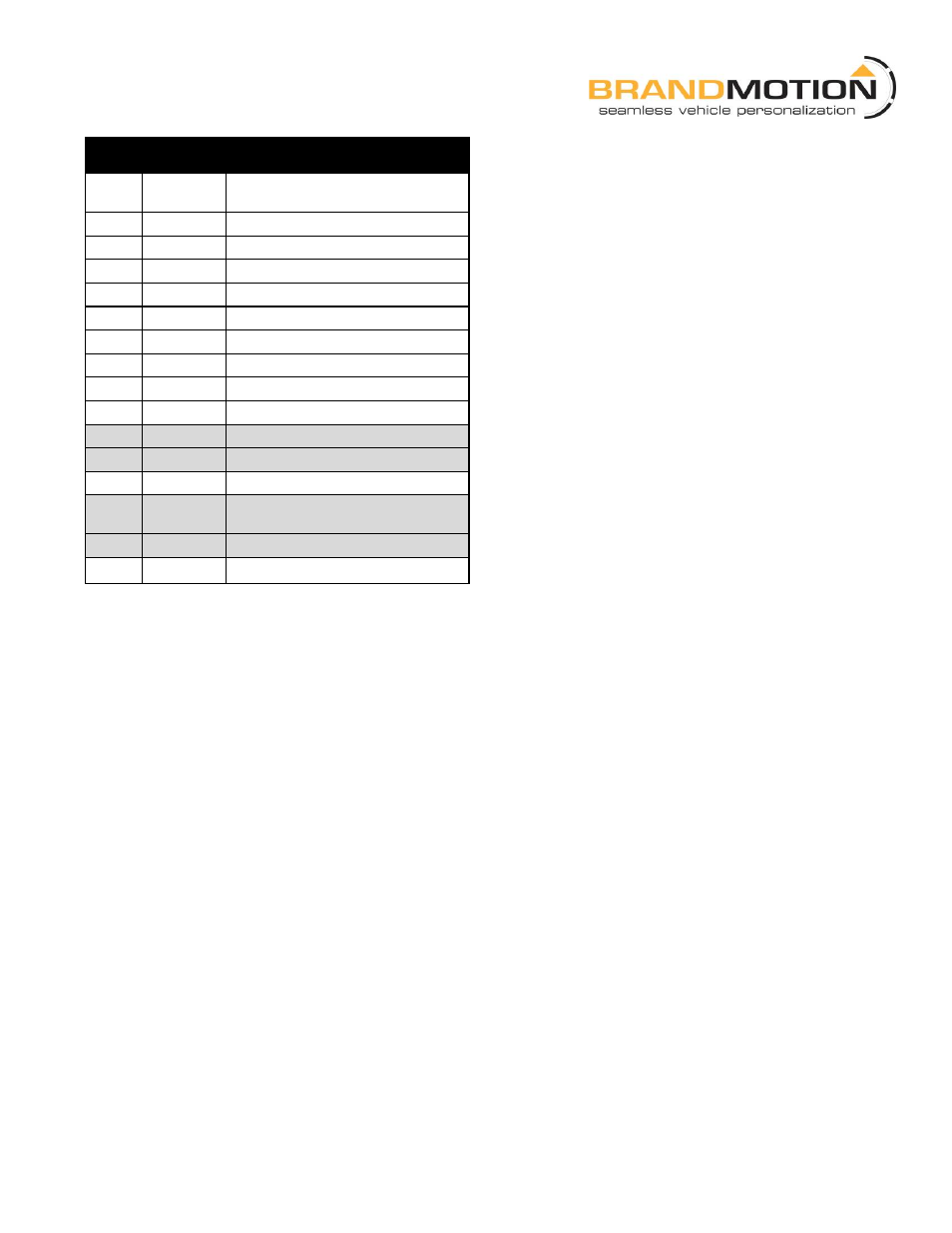
Mirror Harness Pinout*
PIN
WIRE
COLOR
FUNCTION
1
White
Video +
2
Brown
Video -
3 - 4
N/A
N/A
5
N/A
N/A
6
Red
Temp Probe +
7
Black
Temp Probe -
8
Black
Ground
9
Green
Reverse Signal 12V+
10
N/A
N/A
11 †
Varies
OnStar Keypad Signal
12 †
Varies
OnStar Keypad Supply Voltage
13
Red
Ignition Controlled 12V+
14 †
Varies
OnStar Keypad Green LED
Signal
15 †
Varies
OnStar Keypad Red LED Signal
16
N/A
N/A
*These instructions only pertain to functions on the supplied mirror and do not support other vehicle features.
†These pins may be populated in vehicles equipped with OnStar and/or exterior auto dimming mirrors.
Wiring the Mirror:
Red - Ignition controlled power 12v+ when key is turned ON & 14.4 or better when vehicle is running.
Black - Chassis ground
Green - Connect to Reverse + power (reverse lamp)
RCA - Connect to camera video output (See camera requirements above)
Note 1: *5 Orange & *16 White are outside mirror dimming leads which will work on most vehicles with this function
already existing and can purchased separately at Brandmotion under kit number 6014. To maintian outside mirror
dimming function, see separate instructions included in the 6014 kit.
Note 2: If installing on a Ford Motor Company vehicle with a separate display on the IP for the compass AND it displays
“- -“ after the OE mirror is removed, further steps are necessary in in order for it to function again. You must supply two 9’
20-gauge wires (one red and one one yellow recommended) and splice them to the location from which you removed the
vehicle’s mirror connector and to the vehicle’s mirror connector that you will move. For more details, refer to Section 6 of
the 1008-9520 instructions at www.brandmotion.com.