Installation instructions, Mirror harness pinouts, Operating instructions – Brandmotion 9002-8523 User Manual
Page 5
INSTALLATION INSTRUCTIONS
8523 Instructions 7-2-13.doc
Page 5 of 7
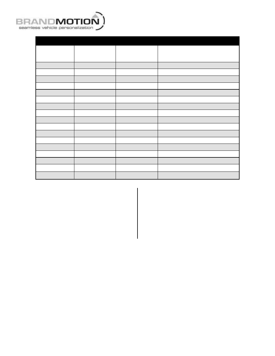
Mirror Harness Pinouts
6-PIN
Pin #
WIRE COLOR
10-PIN
Pin #
WIRE COLOR
16-PIN
Pin #
WIRE COLOR
FUNCTION
1 n/a
n/a
2 n/a
n/a
3 n/a
n/a
4 n/a
n/a
9 - Gray
5 - Gray
Exterior Auto Dimming (+)
1 -White
6 - White
Video +
4 - Brown
7 - Brown
Video -
5 - Black
5 - Black
8 - Black
Ground
3 - Green
1 - Green
9 - Green
Reverse Signal 12V+
10 n/a
n/a
3 - Purple
11 - Purple
Onstar Keypad Signal
4 - Blue
12 - Blue
Onstar Keypad Supply Voltage
6 - Red
2 - Pink
13 - Pink
Ignition Controlled 12V+
6 - Yellow
14 - Yellow
Onstar Keypad Green LED Signal
7 - Orange
15 - Orange
Onstar Keypad Red LED Signal
8 - Red
16 - Red
Exterior Auto Dimming (-)
2 - Blue
Shield
Step 26: Test the system. Inspect that all
connections are proper and secure. Clear all loose
items removed from the area around the vehicle
and turn ignition key ON to test system. Once
reverse gear is engaged the camera image should
appear on the mirror.
Step 27: Secure Chassis Harness and Mirror
Harness with supplied Zip Ties. If necessary,
coil excess harness wire and secure with zip ties.
Attach to existing vehicle wiring where possible.
Step 28: Adjust camera aim. With the aid of an
assistant, move camera to desired view, and
tighten the screws that hold the camera in place.
Step 29: Reassemble vehicle. Follow your
disassembly steps in reverse order, taking care not
to bind the harness wiring when reinstalling trim.
OPERATING INSTRUCTIONS
Temporary Monitor Manual Shut Down. If while in reverse you require to turn OFF the camera
monitor, simply press and release the POWER button on the mirror. (NOTE: once reverse is disengaged the
mirror will go back to normal operation and will turn ON next time reverse is engaged).